Sites
Sites
Path: Tenant -> Config -> Sites
Use the Sites page to create, search, edit, configure, sort, and export tenant sites. The page also provides site-level operations such as VRF association, device replacement, locking, unbinding devices, and license settings.
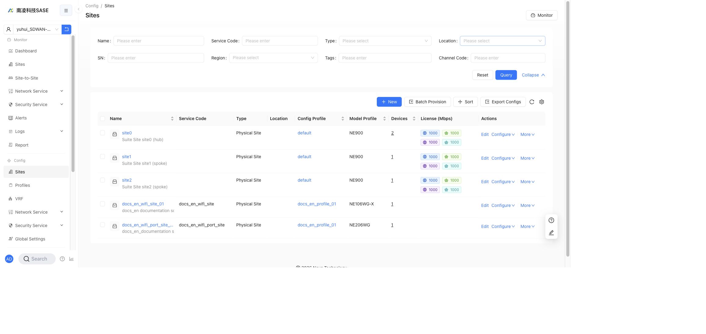
Search and Filter
The default filters are:
Name: search by site name.Service Code: search by service code.Type: filter by site type.
Click Expand to show additional filters:
LocationSNRegionTagsChannel Code
Click Query to apply filters, or Reset to clear them.
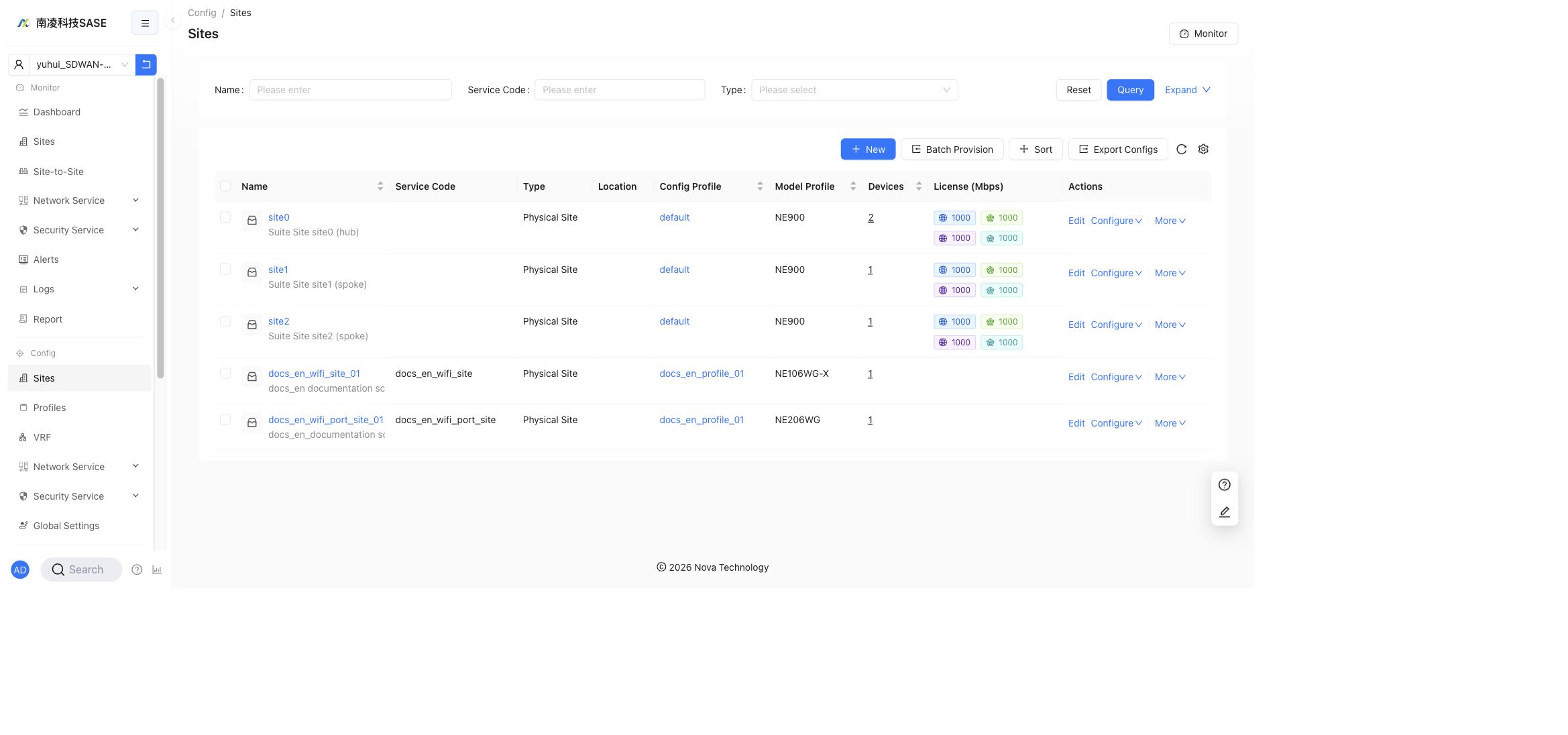
Site List
The table displays the following columns:
Name: site name and description.Service Code: the service code configured for the site.Type: for example,Physical Site.Location: site location information.Config Profile: the configuration profile associated with the site.Model Profile: the hardware model profile.Devices: number of devices bound to the site.License (Mbps): bandwidth licenses for network services.Actions: site-level operations.
Use the toolbar above the table to create sites, batch provision sites, sort sites, export site configurations, refresh the table, or adjust table columns.
Create a Site
Click New to create a site.
The first step is Site Version. The current page recommends New Site, which supports active-standby WAN mode and upcoming features. Legacy Site is kept for compatibility scenarios.
Use New Site for newly deployed sites unless the site must stay compatible with a legacy deployment model. The site version decides which later configuration capabilities are available, especially HA and active-standby WAN behavior.
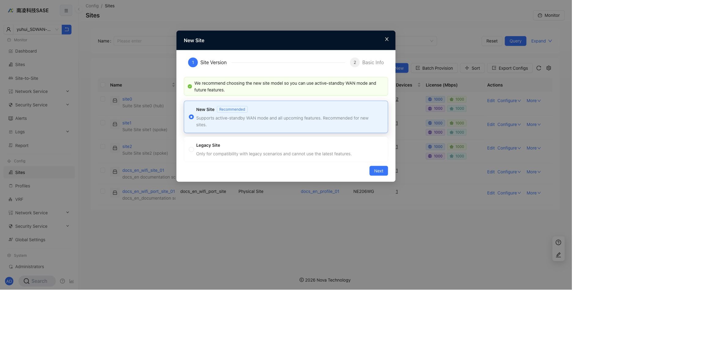
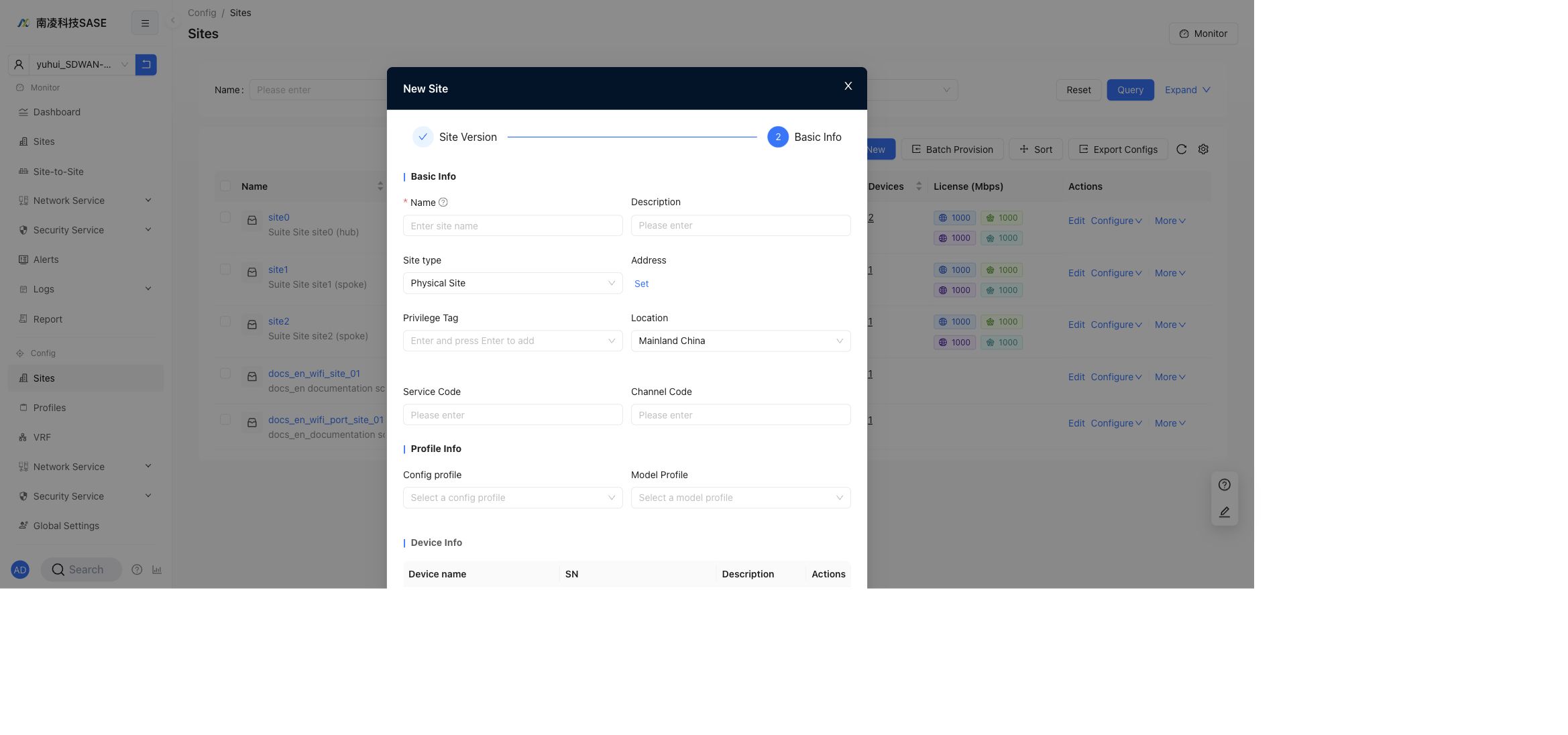
Click Next to enter Basic Info.
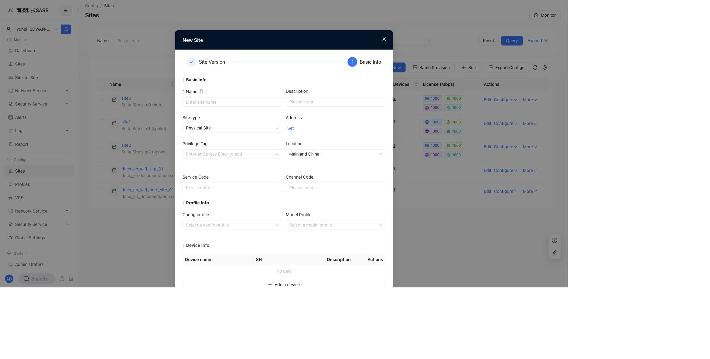
The Basic Info step contains:
Basic Info:Name,Description,Site type,Address,Privilege Tag,Location,Service Code, andChannel Code.Profile Info:Config profileandModel Profile.Device Info: optional device rows withDevice name,SN,Description, andActions.
Field descriptions:
Name: the site name displayed in the site list and configuration pages.Description: optional site description. It is shown below the site name in the list.Site type: the current page usesPhysical Site.Address: set the site address when location information is required.Privilege Tag: assigns permission tags used by tenant operator access control.Location: the site location, for exampleMainland China.Service Code: business service code for search and identification.Channel Code: channel identifier when the tenant uses channel-based management.Config profile: the common configuration profile associated with the site. Common settings can be maintained in a profile and applied to multiple sites.Model Profile: the hardware model profile. It defines the device model, interface count, and interface capabilities available to the site.Device name: the name shown for the bound device.SN: the device serial number. If SN is left empty, the activated device SN is bound automatically. If SN is entered, the activated device must match it.
You can skip adding devices during creation and add them later from the edit dialog. If SN is not specified, the activated device SN is bound automatically. If SN is specified, it must match the activated device.
Edit a Site
Click Edit in the row actions to open the Edit Site dialog.
The edit dialog keeps the same main groups as site creation:
Basic Info: site name, description, site type, address, privilege tag, location, service code, and channel code.Profile Info: config profile and model profile.Device Info: existing device rows.
When editing an existing site, the SN cannot be changed directly. To change the SN, use Device Replacement. Deleting a device from this dialog unbinds it from the site and clears its configuration.
Site Area Configuration
Site areas are used to organize sites into a hierarchy and to limit what tenant operations administrators can view or manage.
Before tenant users can select site areas, enable the feature in the provider tenant settings. In the current English UI, the switch is named Enable hierarchical organization.
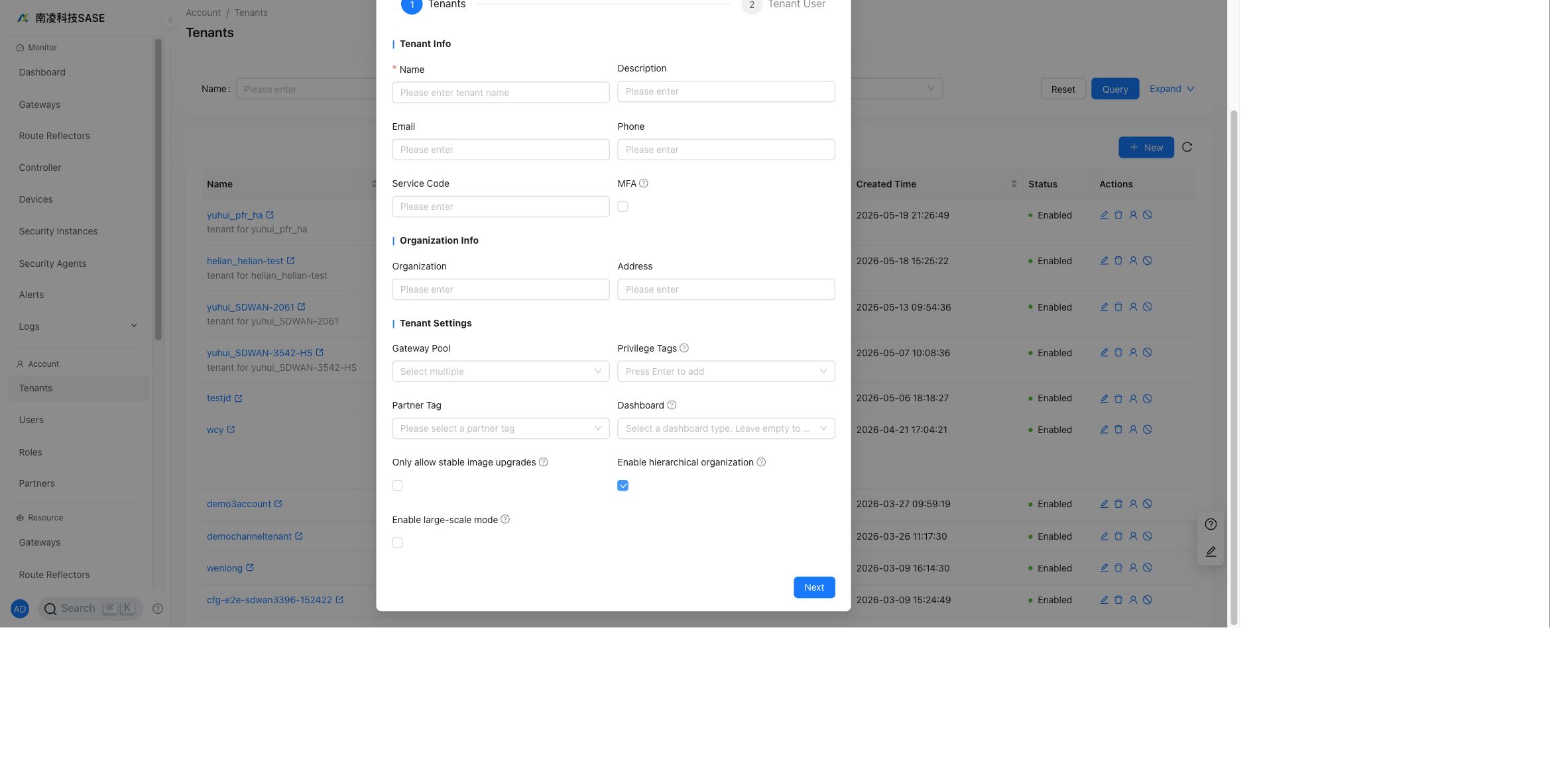
After the feature is enabled, open Tenant -> Config -> Sites. The current English UI shows the area tree as Site Regions and displays Double-click to create region when no root region has been created.
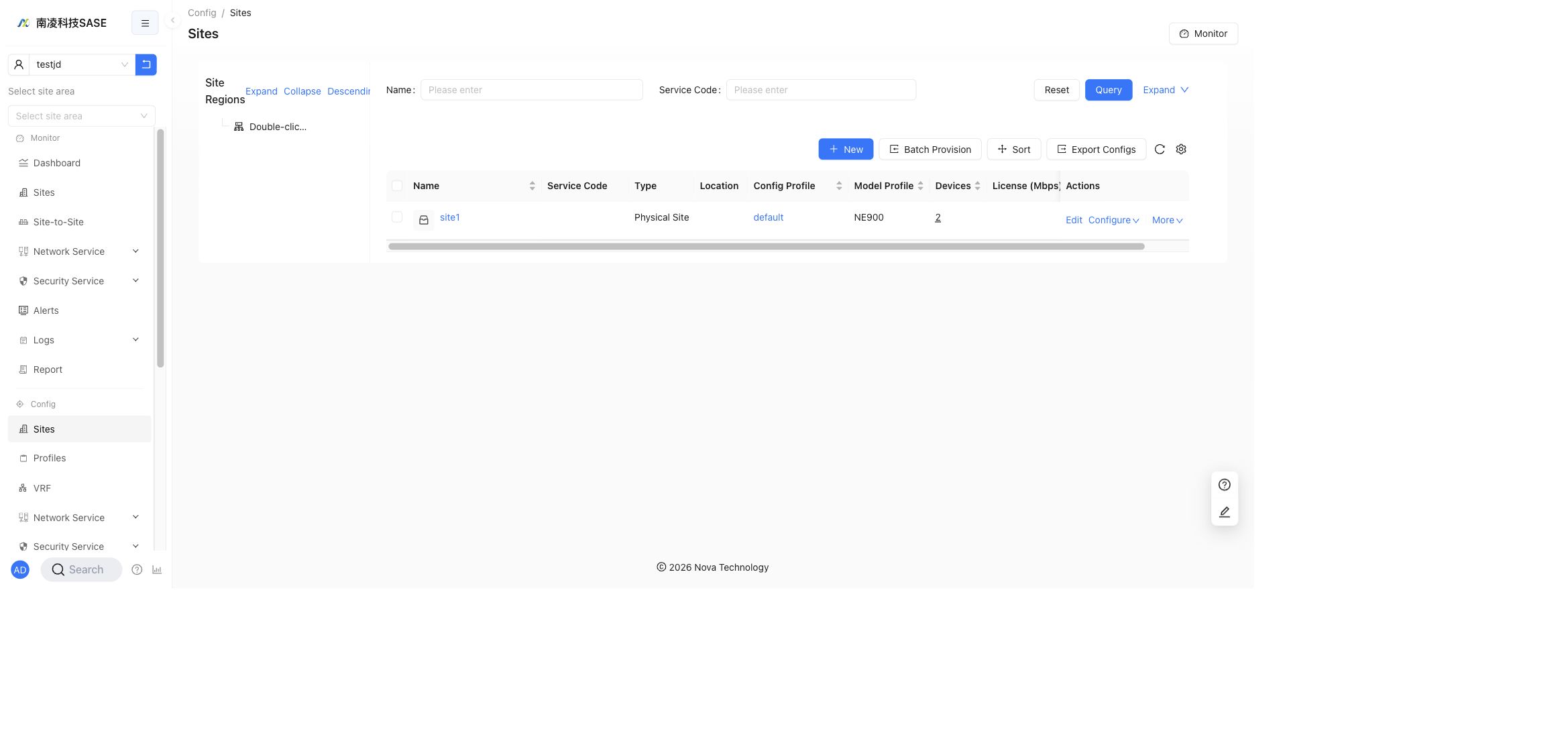
Double-click the empty root position to open Create Sub-region, then enter the region ID and region name.
Region rules:
Region ID: must use letters, numbers, underscores, or hyphens, with 4 to 32 characters. It cannot be duplicated and cannot be changed after creation.Region Name: supports Chinese characters, letters, numbers, underscores, and hyphens, with 1 to 20 characters.- Long Chinese names are shortened in the tree after six Chinese characters. Hover over the name to view the complete value.
- Double-click a region name to rename it. Press
Enteror click outside the field to save the change.
Sites are visible in a site region only after they have matching permission tags. When editing a site, set Privilege Tag in the Edit Site dialog to bind the site to the corresponding region. After the binding is complete, selecting that region shows the sites under the selected region and its child regions.
Hover over the right side of an existing site region to show more operations.
Available operations include:
- Add a child region. The creation rules are the same as creating the root region.
- Rename the site region. You can use the rename action or double-click the region name.
- Delete the site region.
Delete rules:
- If the site region has child regions, it cannot be deleted.
- If the site region has no child regions but contains bound sites, it can still be deleted. The bound sites are automatically moved to the parent region.
After a site region is selected, monitoring pages show only the sites under that region. Site regions can also be assigned to tenant operations administrators so they manage only the corresponding region. See Site area management.
Configure a Site
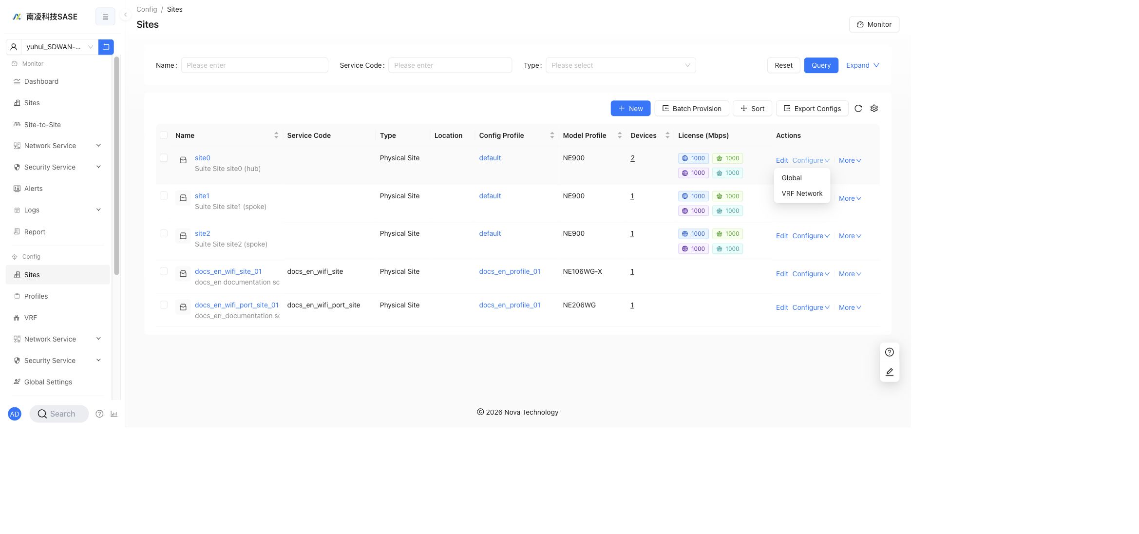
In the row actions, click Configure to open the configuration menu.
The menu contains:
GlobalVRF Network
Enter the site configuration page to configure settings for a single site. Common settings can also be maintained in Config Profile and applied to sites in batches, so profile-based configuration is recommended for settings that should stay consistent across many sites.
The site configuration page contains three main tabs:
Port DefinitionGlobal ConfigurationVRF Configuration
Use Back to return to the site list. Click Save after changing configuration.
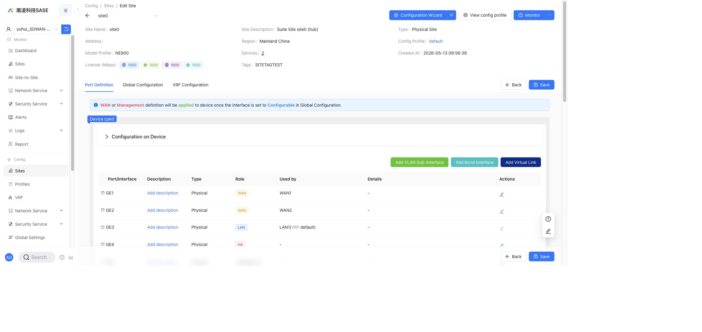
Port Definition
Port Definition shows device interfaces and their roles. It also provides actions to add VLAN Sub-Interface, Bond Interface, and Virtual Link.
WAN or Management definitions are applied to the device after the interface is set to Configurable in Global Configuration.
VLAN Sub-Interface
Use Add VLAN Sub-Interface to create VLAN sub-interfaces on a physical interface or a bond interface.
Notes:
- A physical interface with VLAN sub-interfaces should no longer be used directly as a normal interface.
- Bond interfaces support VLAN sub-interfaces.
- If a bond interface is selected as the HA interconnect interface, VLAN sub-interfaces cannot be added on that bond interface.
- After VLAN sub-interfaces are created on a bond interface, use the bond sub-interface as the LAN interface.
Bond Interface
Use Add Bond Interface to aggregate multiple physical interfaces. The bond interface can then be used by LAN, WAN, or other supported interface roles according to the site model profile.
Virtual Link
Use Add Virtual Link to create a logical interface when the site scenario requires an additional virtual link. The interface role and later usage are configured together with the rest of the port definition and global configuration.
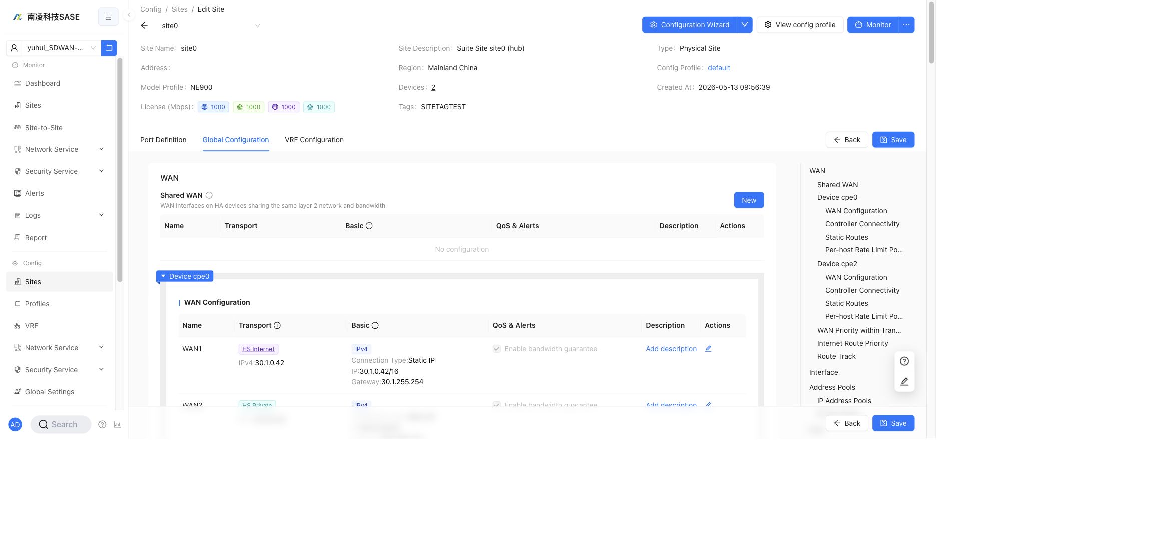
Global Configuration
Global Configuration contains site-wide WAN and device configuration. The current page shows sections such as Shared WAN, device WAN Configuration, Controller Connectivity, Static Routes, Per-host Rate Limit Policies, WAN Priority within Transport Networks, Internet Route Priority, Route Track, Interface, Address Pools, DNS, IPSec, DSCP Marking, Firewall, Features Toggle, and Miscellaneous.
WAN
WAN ports connect the local LAN-side network to the SD-WAN network, remote sites, and the Internet. In HA sites, WAN configuration is organized by Shared WAN, device WAN configuration, and priority or routing policies.
Shared WAN
Shared WAN is used on HA sites where active and standby devices share the same Layer 2 network and bandwidth. Create or edit shared WAN entries from the Shared WAN table.
The table contains:
NameTransportBasicQoS & AlertsDescriptionActions
Shared WAN configuration is maintained in the shared WAN dialog and delivered to both HA devices. Device-specific WAN entries remain under each device section.
WAN Configuration
Each device section contains WAN Configuration. A WAN entry includes Name, Transport, Basic, QoS & Alerts, Description, and Actions.
The Configurable switch controls whether the controller manages and delivers the interface configuration:
- When disabled, the port, sub-interfaces, and related parameters can be saved in the controller but are not delivered to the device.
- When enabled, the controller manages the port and delivers the configuration to the device.
Basic
The Basic configuration covers IPv4, IPv6, and common WAN parameters.
IPv4 connection types:
DHCP: the WAN port obtains an IPv4 address dynamically through DHCP.PPPOE: used for carrier dial-up scenarios. Enter the PPPoE account and password.Static IP: configure the WAN IP address and gateway manually.
IPv6 connection types:
SLAAC: the device obtains the IPv6 address from router advertisements.Static: configure a fixed IPv6 address manually.
Common WAN fields include alternate IP addresses, DNS servers, WAN probing IPs, probing interval, normal and abnormal probe thresholds, and Internet capability controls.
Transport
Transport decides how the WAN builds SD-WAN tunnels.
The supported transport network types are:
Nova PrivateNova InternetHS PrivateHS Internet
Transport settings can include tunnel tags, access IP, interface IP, IPv6 tunnel creation, and WAN optimization such as FEC. FEC can improve audio and video traffic over lossy links, but it increases bandwidth usage, so use it only when packet loss cannot be handled by other optimizations.
QoS and Alerts
QoS & Alerts controls WAN bandwidth, bandwidth guarantee, congestion thresholds, and alerting.
QoS supports four service levels:
GoldSilverBronzeDefault
Configure guaranteed rate, upstream bandwidth, congestion upper and lower thresholds, alert bandwidth, alert threshold, and alert duration according to the site license and WAN bandwidth. Due to tunnel headers, reserve overhead when planning available bandwidth.
Controller Connectivity
Controller Connectivity configures which WAN interface should be preferred when the device connects to the controller. If no entry is configured, the device falls back to default routing.
Fields include:
WAN InterfacePriorityActions
In HA scenarios, the WAN interface selector can include peer options so controller traffic can use the HA interconnect path when needed.
Static Routes
Static Routes configures WAN-side static routes. These routes are not advertised as VRF routes.
IPv4 route fields include:
IP Prefix / RegionNext HopRoute TrackDescriptionActions
IPv6 route fields include IPv6 prefixes, next hop information, directly connected interface options, and description. Associate a route track when the route should automatically become invalid after probing fails.
Per-host Rate Limit Policies
Per-host Rate Limit Policies define rate-limit policies for IP address pools.
Typical fields include:
NameProtocolLimit Rate (Mbps)Address PoolActions
Use these policies to apply source or destination host-level limits based on configured address pools.
WAN Priority within Transport Networks
WAN Priority within Transport Networks adjusts WAN priority inside each transport network. A smaller priority value means higher priority. When multiple WANs have the same priority, traffic can be load-balanced among them.
This priority controls east-west tunnel selection within the same transport. For traffic-class priority, use VRF Configuration -> Traffic Class. For routing priority across transports, use VRF Configuration -> Overlay Routing Policy.
Internet Route Priority
Internet Route Priority configures priority for north-south Internet traffic.
Fields include:
WAN InterfaceMetricWeightActions
Rules:
- A smaller
Metricvalue means higher priority. - If
Metricvalues are different, traffic uses the lower metric first. - If multiple WAN entries use the same
Metric, configureWeightfor load sharing. MetricandWeightuse integer values.
Route Track
Route Track checks reachability of target addresses. It can be referenced by static routes and NAT policies.
Fields include:
NameDescriptionWAN InterfaceTarget AddressesParametersActions
Target addresses support multiple IP addresses separated by commas. If one probe succeeds, the check is considered normal. If probing fails, the referenced route or NAT policy can become inactive until the track recovers.
Interface
The Interface section contains management and HA interface settings.
Management Interface
Management Interface configures management parameters for each device. Use the Configurable switch to decide whether the controller delivers the management interface configuration.
Management interface settings can include DHCP, static IP, gateway IP, DHCP server address range, and Wi-Fi management options when supported by the device model.
High Availability
High Availability controls whether HA is enabled for the site and which device is the primary member device.
HA notes:
- HA is only available for supported site models and device versions.
- The HA interconnect interface is used for heartbeat and failover.
- Changing HA settings can affect transport priorities and traffic path selection.
HA Interconnect
HA Interconnect shows HA member devices and their interconnect IP addresses. Advanced options can be used to adjust HA interconnect parameters such as MTU when required.
Changing HA interconnect IP may interrupt traffic. If changed, the primary and standby HA IPs must be valid non-broadcast addresses in the same /30 or /31 subnet.
Address Pools
Address Pools contains IP Address Pools and IP Port Pools. These pools are used by NAT policies and other address-based features.
IP Address Pools
IPv4 address pools define public IPv4 address ranges for SNAT and DNAT. Pools can be shared across VRFs or dedicated to a specific VRF.
IPv6 address pools define public IPv6 prefixes for IPv6 NAT. IPv6 pools are dedicated pools and are associated with a VRF.
Important rules:
- Address pools referenced by NAT policies cannot be deleted or changed to incompatible configurations.
- In HA sites, IPv4 pools can bind to shared WAN or device WAN according to the policy scope.
- IPv6 address pools do not support shared WAN binding.
- Site-level shared and dedicated pools cannot use the same address range.
IP Port Pools
IP Port Pools allocate one or more IP addresses and ports from an IPv4 shared address pool. They are commonly used as DNAT destination match objects.
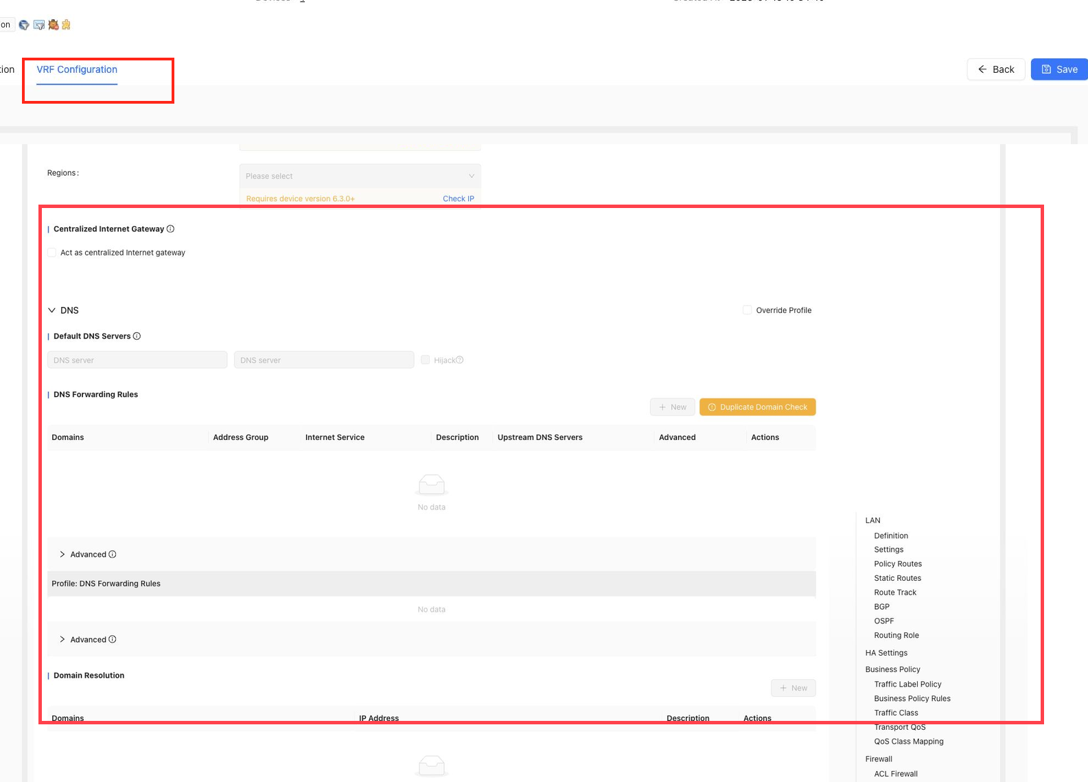
DNS
DNS contains Default DNS Servers and Domain Resolution.
Default DNS servers can override WAN DNS configuration. When two DNS servers are configured, the device sends DNS queries to both and uses the first response.
Domain resolution supports proxy DNS rules, local DNS records, and IPv4 or IPv6 resolution controls.
IPSec
IPSec controls site-level encryption parameters when they need to override profile configuration.
Supported encryption algorithms include SM series algorithms, AES256, AES128, and NULL, depending on device and profile support. IKE, server, and NAT-T ports can also be configured when required.
DSCP Marking
DSCP Marking maps service levels to underlay DSCP tags. It is commonly used with carrier SLA classes such as Gold, Silver, Bronze, and Default.
Firewall
Firewall contains Device Service Firewall. Use it to protect device-side services and reduce scanning exposure from the WAN side.
Features Toggle
Features Toggle controls site-level feature switches.
The current page includes:
SNMPIPv6Internet serviceTransparent mode
Notes:
- SNMP supports SNMPv1/v2 and SNMPv3.
- IPv6 requires a supported device version.
- Internet service requires a supported device version.
- Transparent mode requires a supported device version and is not available for HA sites.
Miscellaneous
Miscellaneous contains auxiliary site settings such as device password management, NTP/timezone settings, and activation-time upgrade behavior.
Use these settings when a single site must override the profile-level default.
VRF Configuration
VRF Configuration contains VRF-level network settings. The current page shows VRFs, Network, LAN, Definition, Settings, Policy Routes, Static Routes, Route Track, BGP, OSPF, Routing Role, HA Settings, Business Policy, Firewall, Authentication Policy, NAT, TCP Optimization, GRE Tunnel, Local Breakout, DNS, and Routing Policy.
LAN
LAN contains Definition, Settings, Policy Routes, Static Routes, Route Track, BGP, OSPF, and Routing Role.
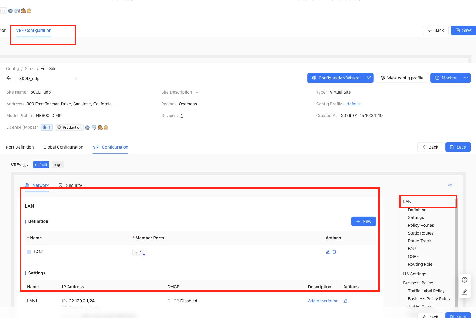
Definition
Definition creates LAN names and member ports. Multiple LANs and VLAN sub-interfaces are supported according to the port definition.
Fields include:
NameMember PortsActions
Settings
Settings configures LAN IP address, DHCP, advertise route behavior, IPv6 link-local address, and description.
Typical fields include:
NameIP AddressDHCPDescriptionActions
DHCP settings can include address range, DHCP options, static bindings, and import/export of DHCP static binding data when available.
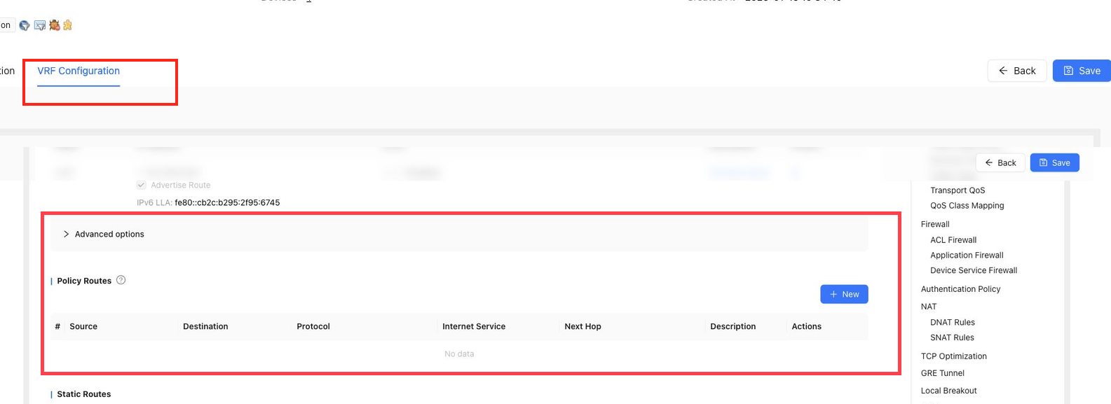
Policy Routes
Policy Routes forward traffic based on match conditions.
Policy route settings include:
SourceDestinationProtocolInternet ServiceNext HopDescriptionActions
Policy routes usually have the highest priority because they match traffic by configured policy. For routes with the same prefix length, static routes are preferred over dynamic routes.
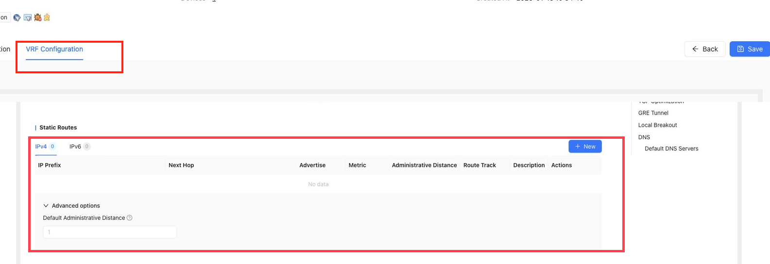
Static Routes
Static Routes configure fixed forwarding paths for the current VRF. Both IPv4 and IPv6 routes are supported.
Fields include:
IP PrefixNext HopAdvertiseMetricAdministrative DistanceRoute TrackDescriptionActions
Notes:
- Next hop
WANsends traffic out of the local WAN instead of the east-west tunnel. - Next hop
BLACK HOLEcreates a null route. Metriccontrols route priority within the same protocol. A larger metric means lower priority.Administrative Distancecontrols protocol priority. A larger value means lower priority.- Region-based route destinations are supported, but large region combinations may exceed device limits.
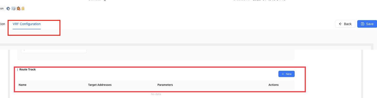
Route Track
VRF Route Track checks target addresses and can be referenced by VRF static routes. If probing fails, the related route can be withdrawn. When probing recovers, the route becomes active again.
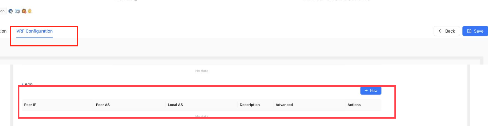
BGP
BGP configures dynamic routing peers for the current VRF.
Fields include:
Peer IPPeer ASLocal ASDescriptionAdvancedActions
Advanced BGP settings can include password, keepalive interval, hold time, Exclude AS, maximum advertised routes, maximum received routes, AS Path Prepend length, AS Override, route advertisement policy, and route receiving policy.
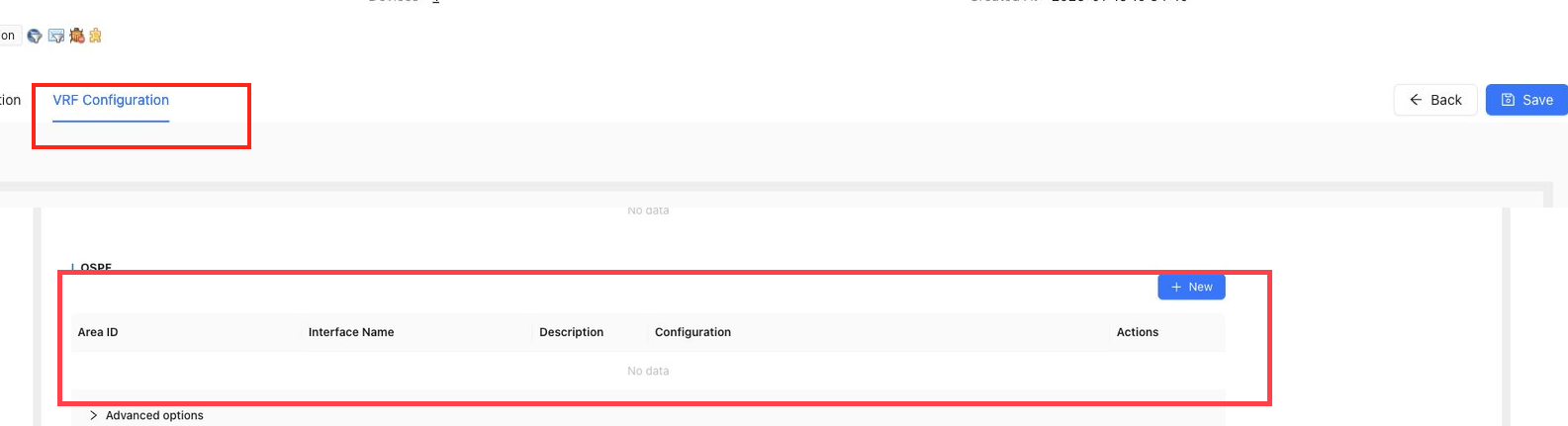
OSPF
OSPF configures dynamic routing with LAN-side devices.
Fields include:
Area IDInterface NameDescriptionConfigurationActions
Supported options can include network type, Hello interval, dead interval, authentication key ID, password, default metric, external route type, route advertisement policy, and route receiving policy.
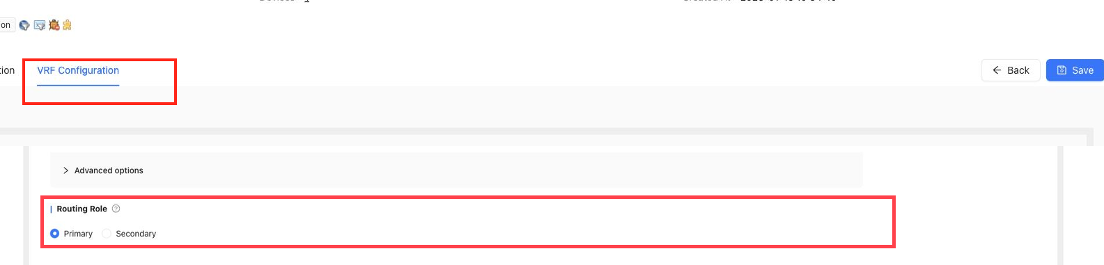
Routing Role
Routing Role is used for primary and secondary site routing scenarios. When two sites advertise the same LAN route, configure the primary site with higher advertisement priority and the secondary site with lower priority.
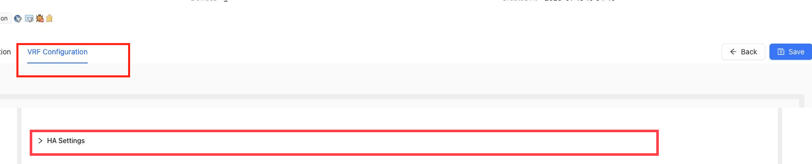
HA Settings
HA Settings configures VRF-level HA information such as backup IP and VRRP probing.
Notes:
- The LAN IP can act as the VRRP VIP, while backup IPs represent the real device IPs.
- VRRP probe addresses support multiple comma-separated IP addresses.
- In MultiVRF scenarios, HA settings should remain consistent between the HA member devices.
Business Policy
Business Policy classifies and schedules traffic. It supports matching by IP five-tuple, application group, DSCP, traffic labels, and other conditions. It can apply queue priority, traffic shaping, DSCP remarking, path selection, and bandwidth guarantees.
The current page groups business policy settings as:
Traffic Label PolicyBusiness Policy RulesTraffic ClassTransport QoSQoS Class Mapping
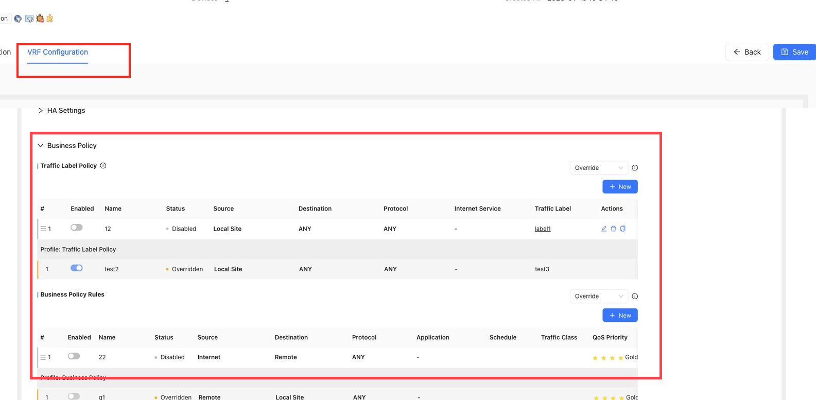
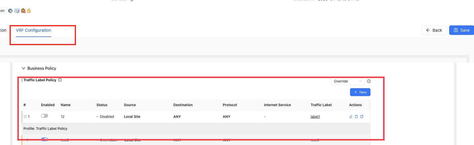
Traffic Label Policy
Traffic Label Policy classifies traffic by L3/L4 match conditions such as source, destination, protocol, port, and DSCP, then applies a configured traffic label. Traffic labels can later be used by business policy and scheduling rules.
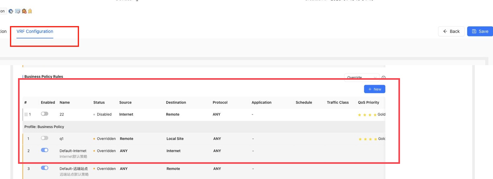
Business Policy Rules
Business Policy Rules define the service guarantee behavior for matched traffic. Traffic can be scheduled by service class, bandwidth limit, and path selection policy.
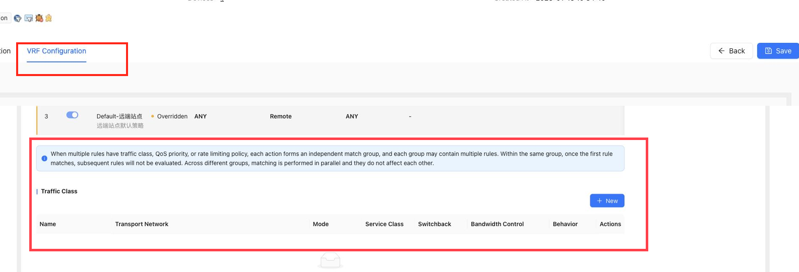
Traffic Class
Traffic Class defines service levels and the handling behavior for traffic classes such as Gold, Silver, Bronze, and Default.
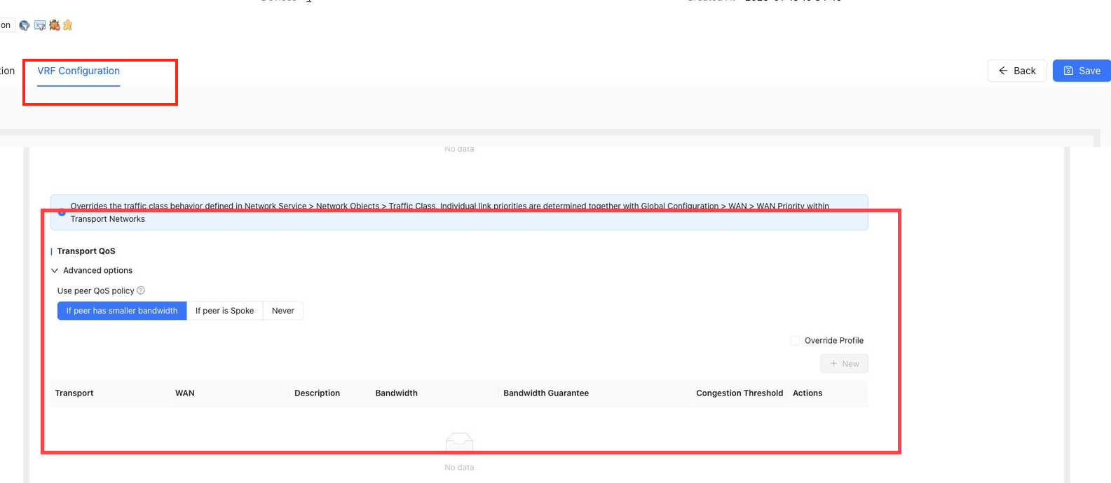
Transport QoS
Transport QoS configures bandwidth, congestion thresholds, alert duration, and guaranteed-rate percentages for transport networks.
When using tunnel transport, reserve bandwidth for tunnel headers. A common planning rule is to set QoS bandwidth lower than raw WAN bandwidth.
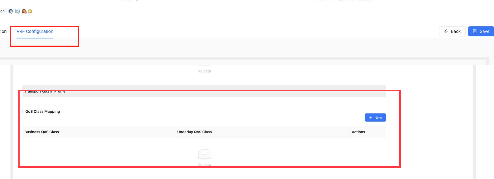
QoS Class Mapping
QoS Class Mapping maps business traffic classes to underlay QoS classes. By default, traffic can be mapped to a default underlay class unless customized.
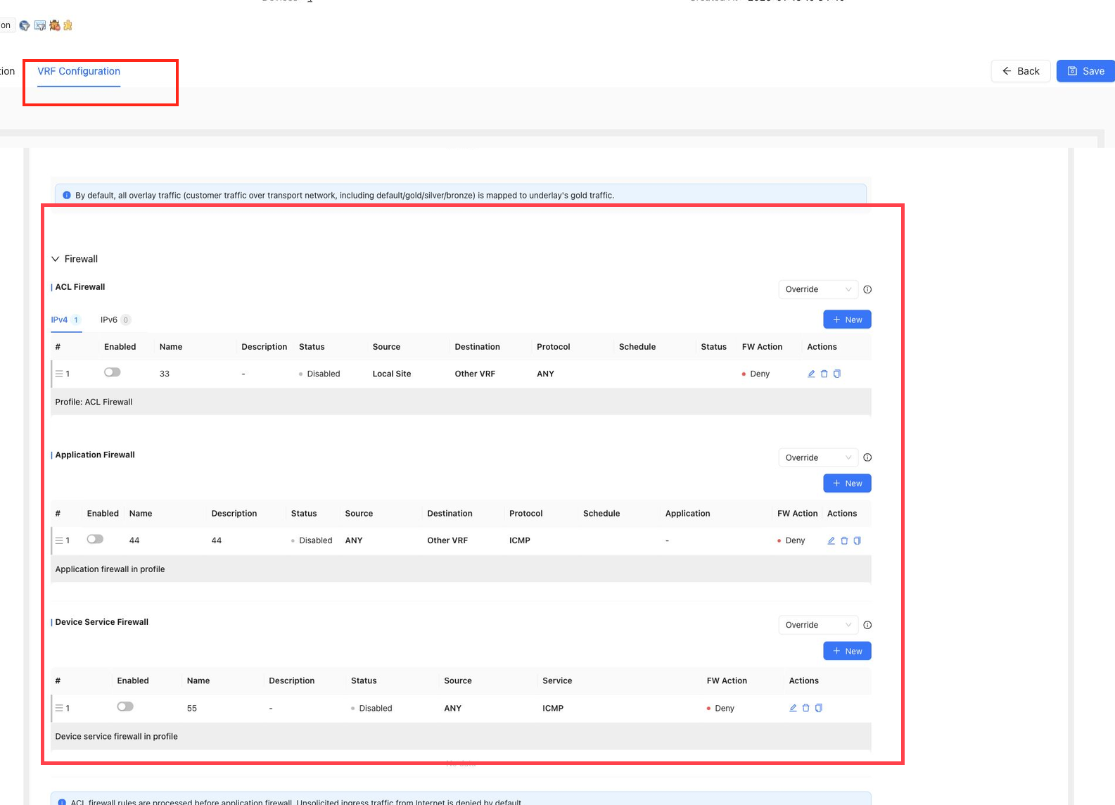
Firewall
Firewall contains:
ACL FirewallApplication FirewallDevice Service Firewall
Firewall rule matching uses an AND relationship across all match conditions. Rules are matched from top to bottom, and matching stops after the first hit. ACL firewall rules take precedence over application firewall rules.
Firewall conditions can reference sites, security groups, IP prefixes, application objects, and services according to the selected rule type.
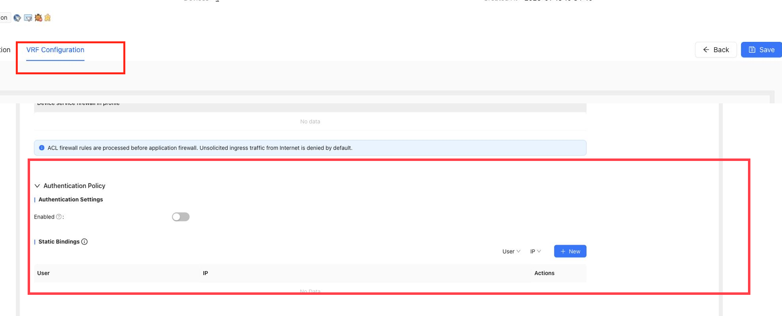
Authentication Policy
Authentication Policy controls local user authentication for the site.
It includes:
Authentication SettingsStatic Bindings
Authentication settings can enable or disable local authentication, set the authentication method, configure authentication address ranges, configure authentication-free addresses, and choose destination whitelist address groups.
Static bindings associate a user with an IP address. A statically bound user is exempt from authentication for the configured IP. One IP can only be bound to one user.
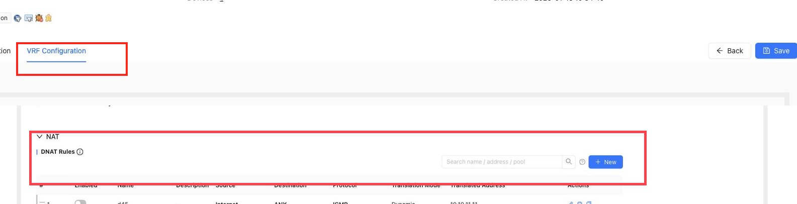
NAT
NAT contains DNAT Rules and SNAT Rules.
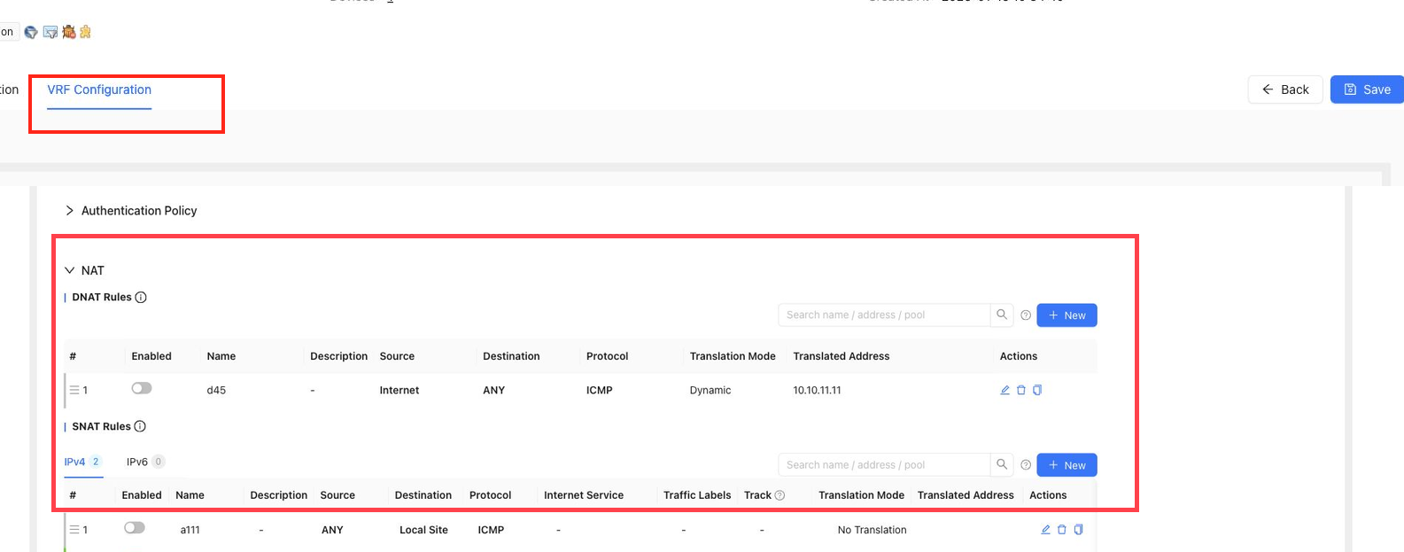
DNAT Rules
DNAT maps the pre-translation destination address, protocol, and port to a post-translation address and port. It is used when internal services need to be reachable from outside.
DNAT settings include:
Rule NameDescriptionSourceDestinationProtocol/PortTranslation ModeTranslated IP/Port
Notes:
- Internet-side DNAT destination objects are managed through address pools.
- IP port conversion supports one-to-one and one-to-many mapping.
- Address pools referenced by DNAT cannot be deleted or changed to incompatible settings.
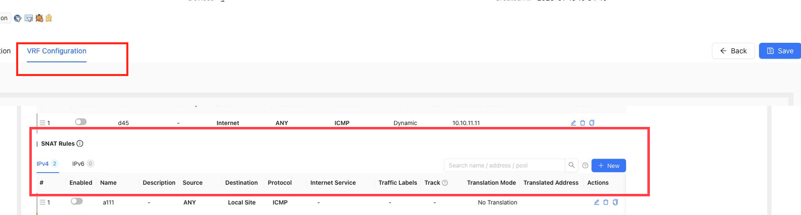
SNAT Rules
SNAT maps source addresses to translated source addresses or outbound interface addresses. It lets internal hosts access external networks through translated addresses.
SNAT settings include:
Rule NameDescriptionDeviceSourceDestinationProtocol/PortTraffic LabelTrackInternet ServiceTranslation ModeTranslation TargetWAN Interface
SNAT can use dynamic NAT, static NAT, or no translation. In HA sites, rules can be scoped by device, shared WAN, or device WAN according to the selected target.
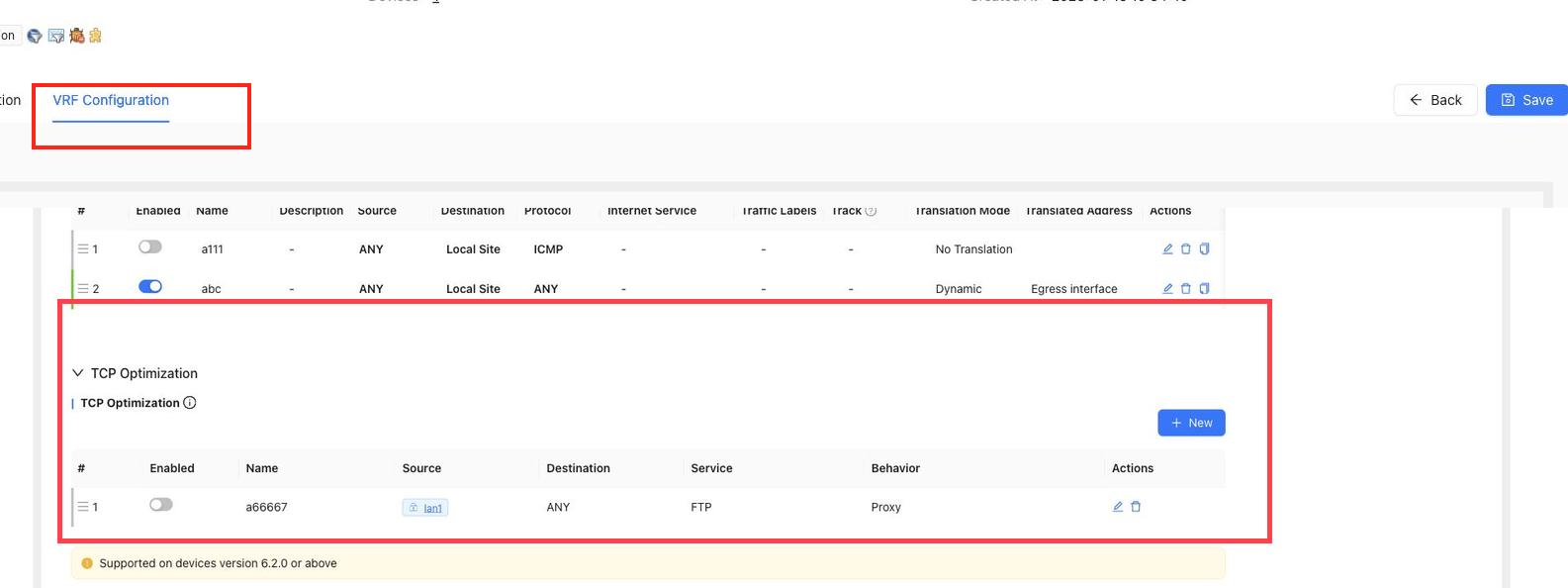
TCP Optimization
TCP Optimization improves throughput for selected TCP services when SD-WAN latency is high or link quality is poor. It should be configured close to the traffic sender.
Notes:
- Match conditions can use either IP addresses or address groups, but do not mix both in the same source or destination condition.
- Service and service port are mutually exclusive selections.
- Optimization rules are matched in order.
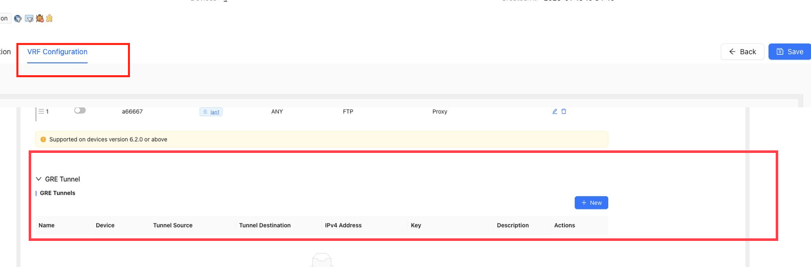
GRE Tunnel
GRE Tunnel creates standard GRE tunnels in a VRF for cross-network communication. A common use case is connecting a cloud site to a remote transit gateway.
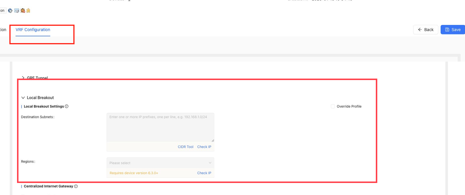
Local Breakout
Local Breakout controls whether traffic exits through the local WAN.
Use it for:
- Local Internet breakout for selected destination IPs or regions.
- Centralized Internet gateway scenarios where this site acts as the Internet egress for other sites.
Destination subnets can be prepared with the CIDR tool and validated before saving.
DNS
VRF-level DNS includes:
Default DNS ServersDNS Forwarding RulesDomain Resolution
Default DNS servers can override WAN DNS. DNS forwarding rules send specified domains to specified DNS servers. Local domain resolution defines local A records. Domain resolution policies can disable IPv4 or IPv6 resolution.
The same domain should only appear in one DNS forwarding rule. Duplicate domain detection can be used before or after saving rules.
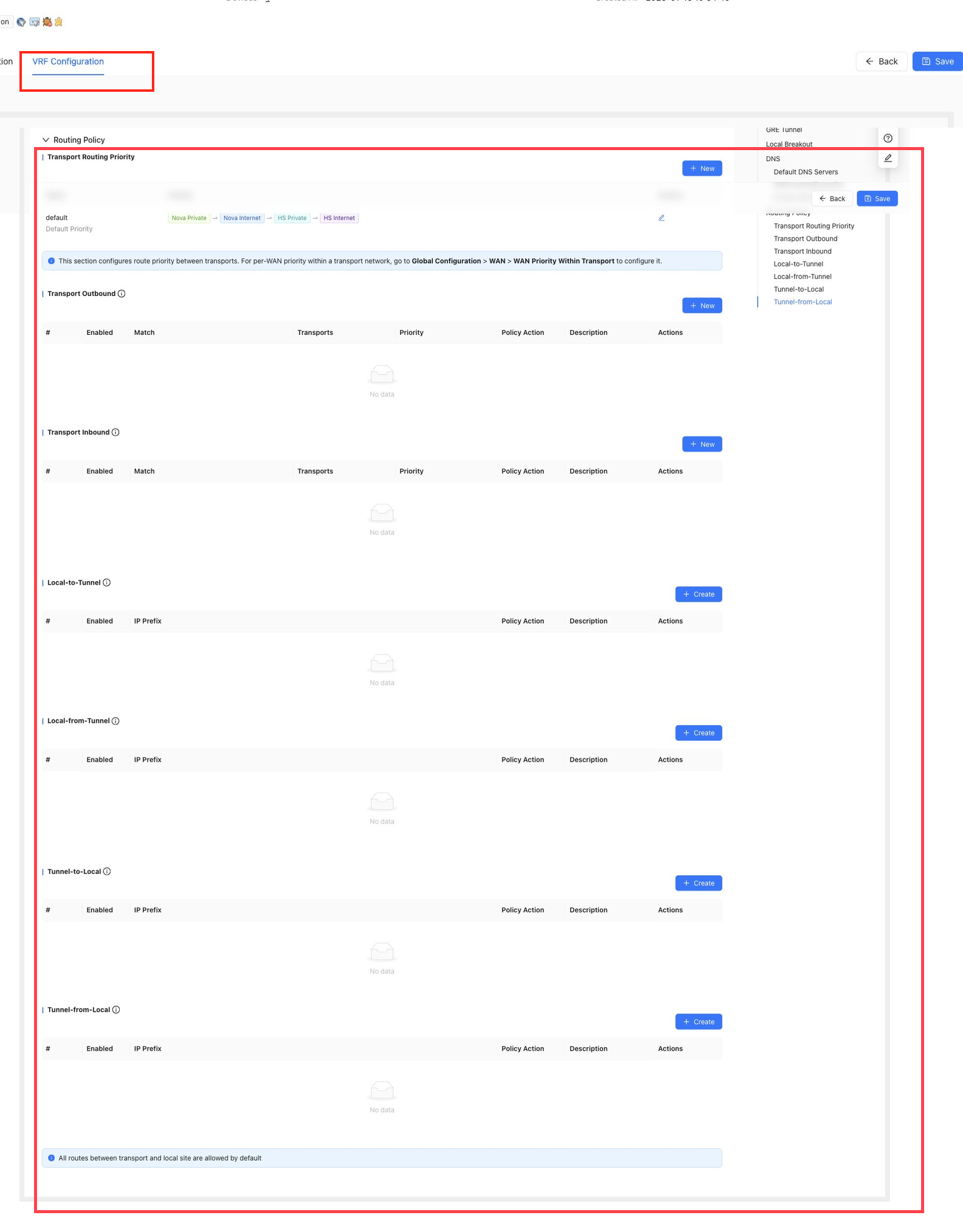
Routing Policy
Routing Policy controls overlay route advertisement, receiving, and transport selection.
The current page includes:
Transport Routing PriorityTransport OutboundTransport InboundLocal-to-TunnelLocal-from-TunnelTunnel-to-LocalTunnel-from-Local
Routing policy supports per-prefix route priority, site route priority, and advertisement or receiving filters. Advertisement filtering is based on IP prefix. Receiving filters can be based on site, gateway, or IP prefix.
VRF Security Configuration
When security features are enabled for a site or VRF, security configuration can include security service policies, URL filtering profiles, file filtering profiles, content filtering profiles, mail filtering profiles, anti-virus profiles, vulnerability protection profiles, anti-spyware profiles, attack protection, session limits, allowlists, blocklists, custom internal addresses, and advanced parameters.
Use templates for common security configuration when possible. Override the template at the site only for settings that require site-specific customization.
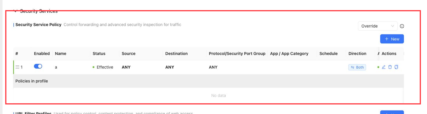
Security Services
Security Services contains security policy and security profile configuration for application-aware inspection and content control.
Security Service Policy
Security Service Policy controls forwarding and advanced security inspection for traffic.
Security policy rules match traffic by source, destination, protocol or security port group, application or application category, schedule, direction, and action. Rules are matched in order. If logging is enabled, matched rules are recorded as logs.
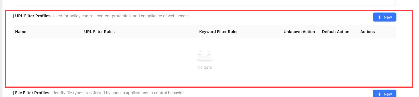
URL Filter Profiles
URL Filter Profiles are used for web access policy control, content protection, and compliance.
They can include URL filter rules, keyword filter rules, unknown URL actions, and default actions.
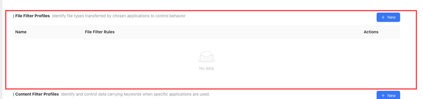
File Filter Profiles
File Filter Profiles identify file types transferred by selected applications and control file transfer behavior.
Common protocols include FTP, HTTP, SMTP, POP3, IMAP, and SMB. Files that exceed the supported decompression size can be allowed without file filtering.
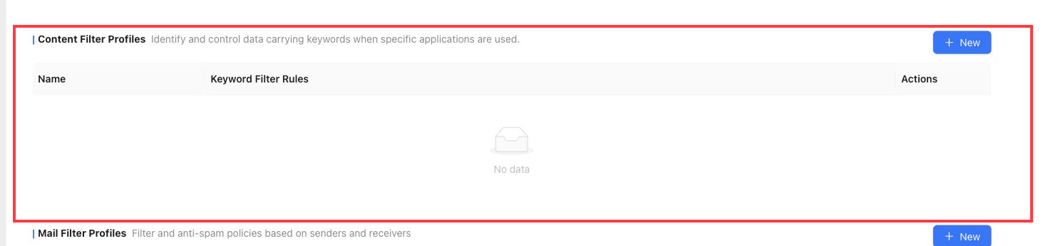
Content Filter Profiles
Content Filter Profiles identify and control data that carries configured keywords.
They can apply to supported file types such as HTML, TXT, DOC, DOCX, XLS, XLSX, PPT, PPTX, PDF, RTF, XML, and other document formats.
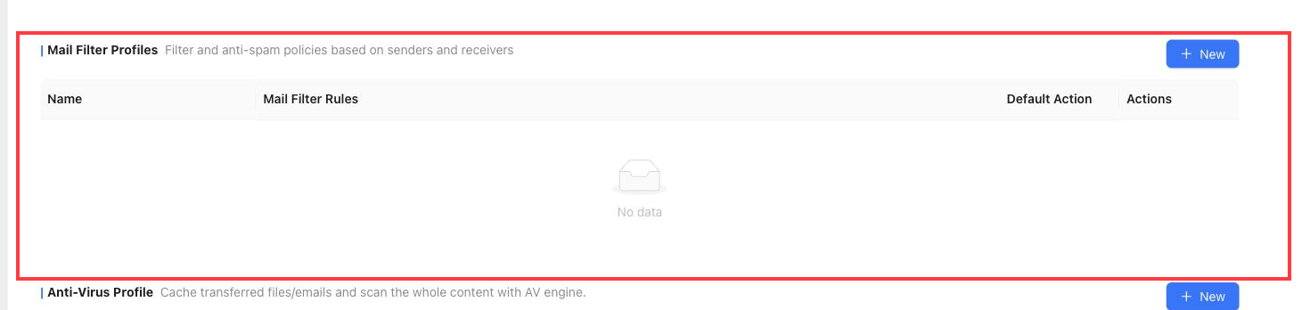
Mail Filter Profiles
Mail Filter Profiles provide mail filtering and anti-spam control based on senders and receivers.
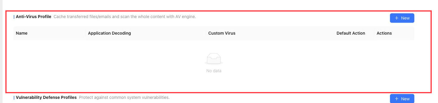
Anti-Virus Profile
Anti-Virus Profile scans transferred files or mail after decoding and caching the content.
Application decoding can cover HTTP, SMB, FTP, SMTP, POP3, and IMAP traffic. Custom viruses supplement the AV signature database and take precedence during matching.
Vulnerability Defense Profiles
Vulnerability Defense Profiles protect traffic against common system vulnerabilities.
Exception rules can be used when specific traffic must bypass a protection rule.
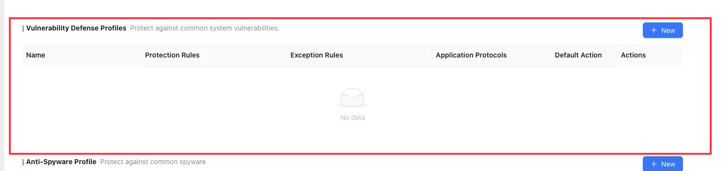
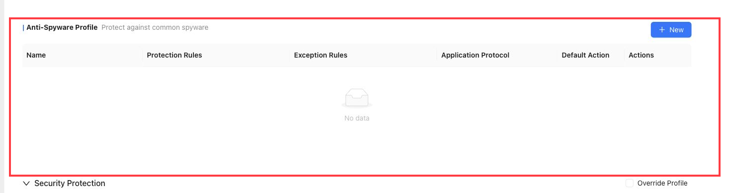
Anti-Spyware Profile
Anti-Spyware Profile protects against common spyware traffic.
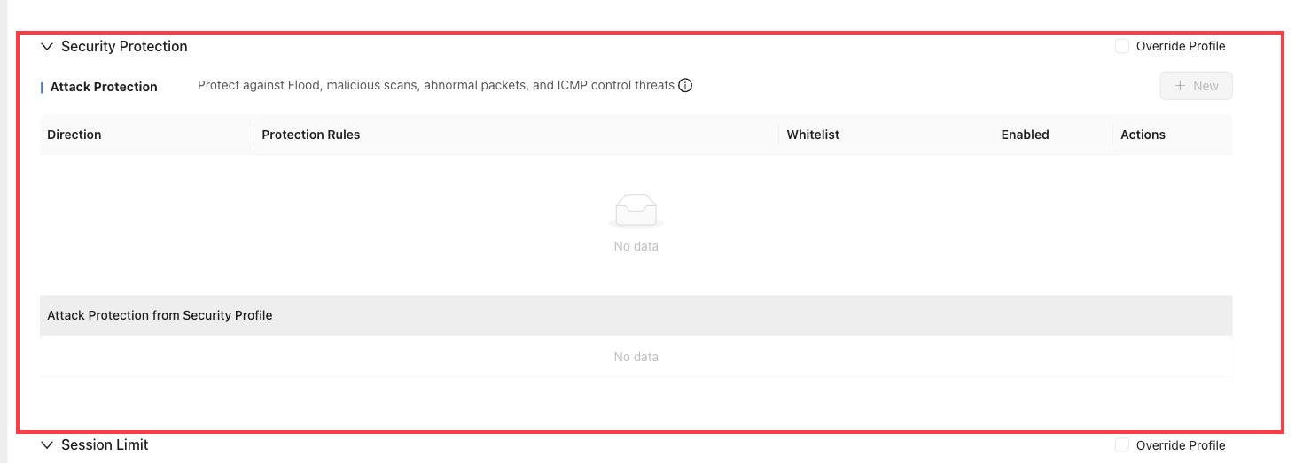
Security Protection
Security Protection contains attack protection settings.
Attack Protection
Attack Protection protects against Flood attacks, malicious scans, abnormal packet attacks, and ICMP control threats.
Addresses in the attack protection whitelist bypass attack protection inspection. Threshold values define when the protection action is triggered.
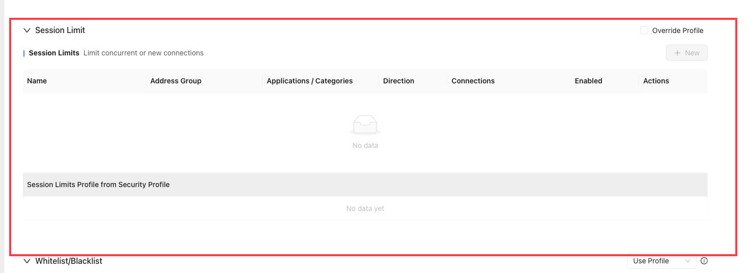
Session Limit
Session Limit limits concurrent connections or new connection rates.
Use this section to prevent abnormal traffic from consuming too many sessions. A value of 0 means no limit for the corresponding field.
Whitelist/Blacklist
Whitelist/Blacklist contains IP and domain allowlist or blocklist controls.
IP Whitelist
IP addresses in the whitelist are exempt from security inspection such as file filtering, content filtering, mail filtering, anti-virus, vulnerability protection, anti-spyware, session limit, threat intelligence, and response-center checks.
The IP whitelist applies to source IP addresses and takes precedence over the blacklist.
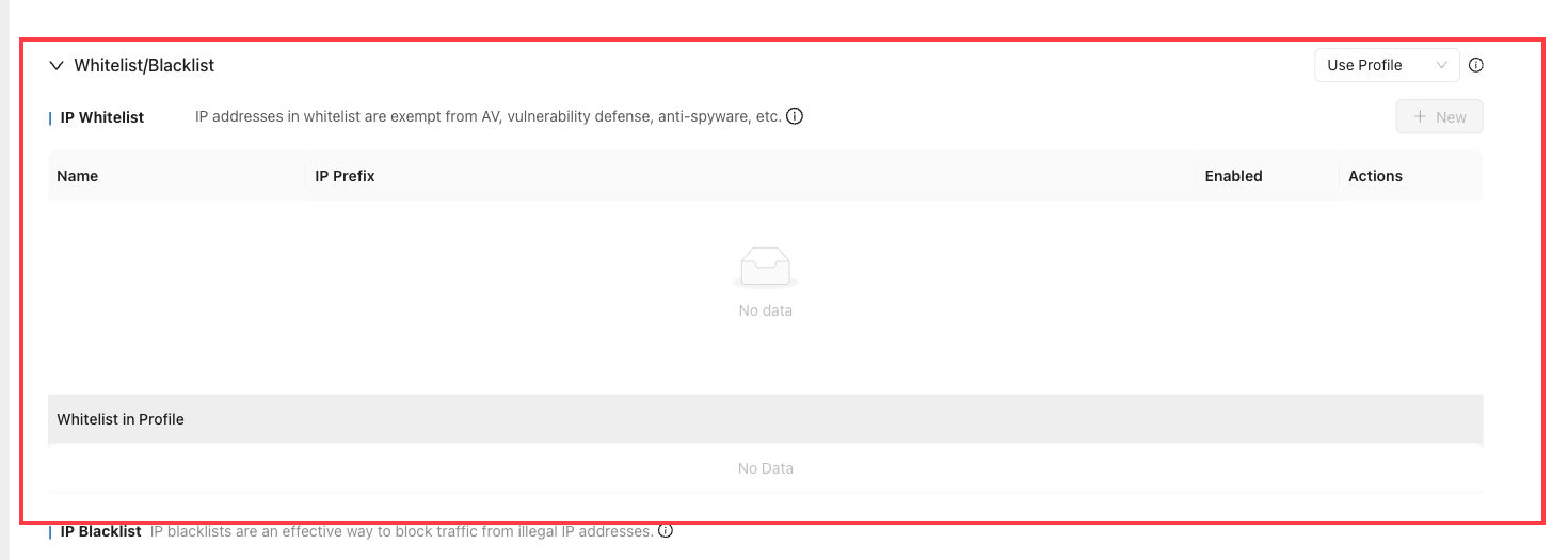
IP Blacklist
IP Blacklist blocks traffic from illegal or unwanted source IP addresses.
IP blacklist rules take precedence over security policies and other policy controls.
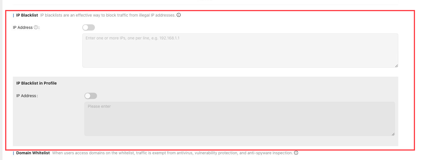
Domain Whitelist
Domain Whitelist exempts access to configured domains from anti-virus, vulnerability protection, anti-spyware, and threat intelligence checks.
Domain whitelist rules take precedence over domain blacklist rules.
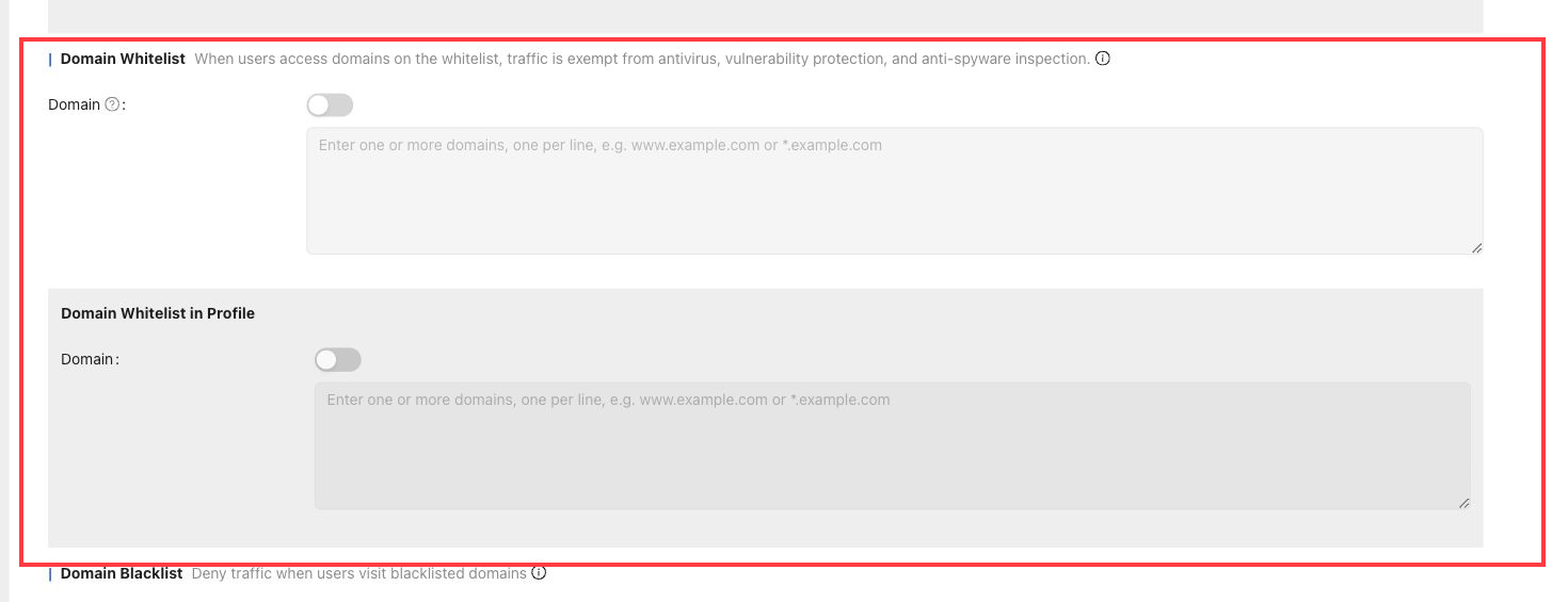
Domain Blacklist
Domain Blacklist denies traffic when users access configured blacklisted domains.
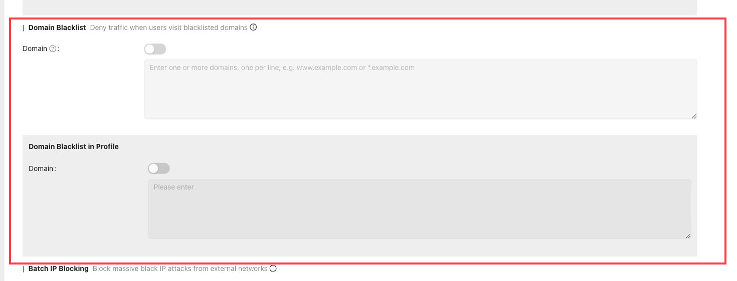
Batch IP Blocking
Batch IP Blocking blocks a large number of blacklisted external IP addresses from attacking internal hosts.
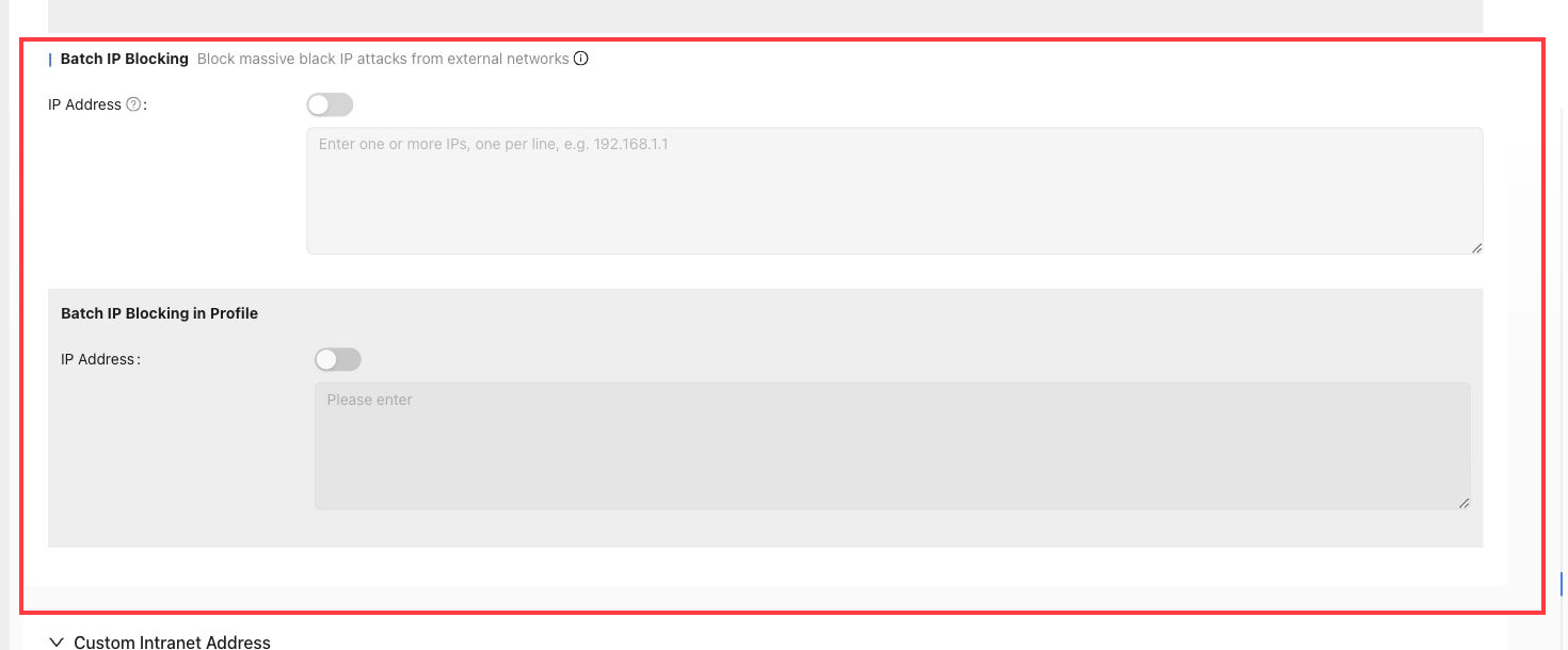
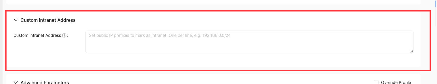
Custom Intranet Address
Custom Intranet Address marks specified public IP prefixes as intranet addresses.
Use it when address libraries incorrectly classify traffic addresses and the site security policy must treat those prefixes as internal addresses.
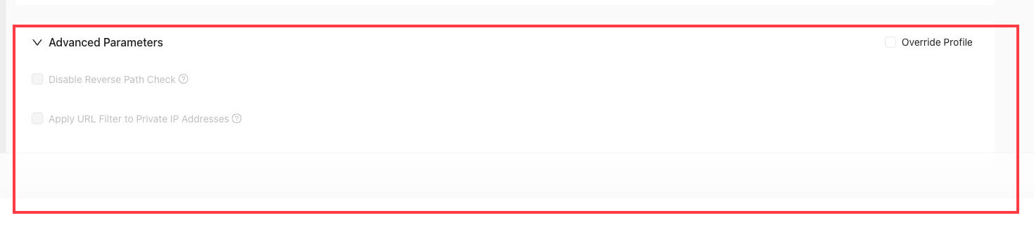
Advanced Parameters
Advanced Parameters contains additional site security behavior controls.
Disable Reverse Path Check: allows asymmetric paths when selected.Apply URL Filter to Private IP Addresses: applies URL filtering even when the URL resolves to a private IP address.
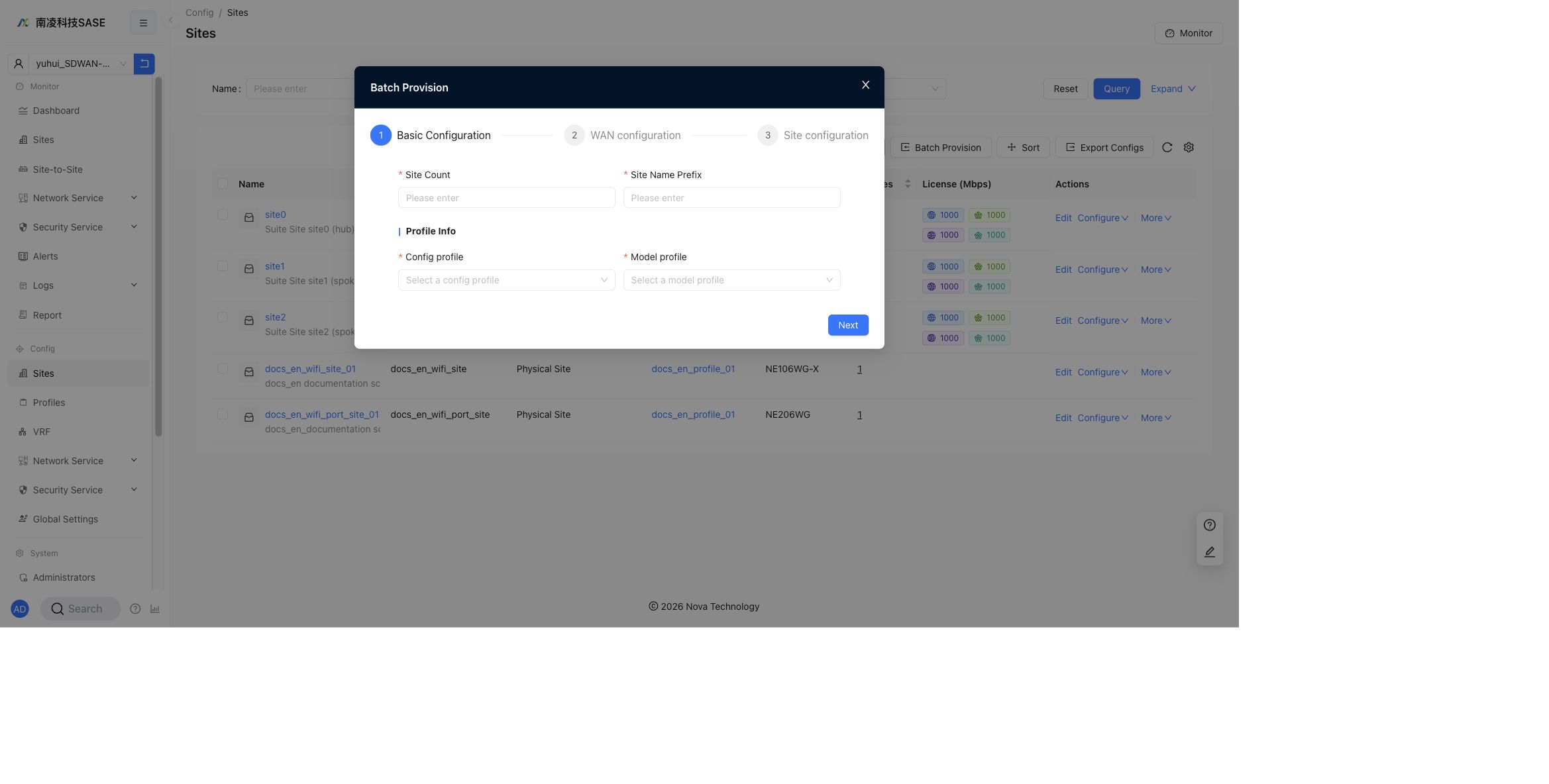
Batch Provision
Click Batch Provision to create multiple sites through a wizard.
The wizard includes:
Basic Configuration: setSite Count,Site Name Prefix,Config profile, andModel profile.WAN configuration: configure WAN settings for the generated sites.Site configuration: complete site-level configuration before provisioning.
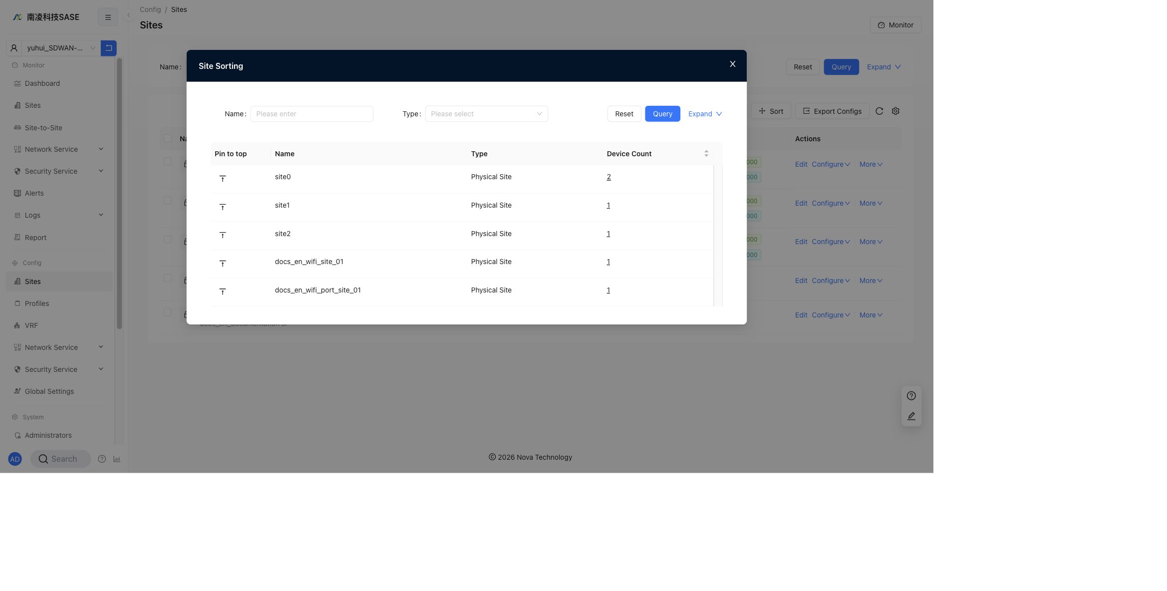
Sort Sites
Click Sort to open Site Sorting.
The sorting dialog supports searching by Name and Type. The table shows Pin to top, Name, Type, and Device Count.
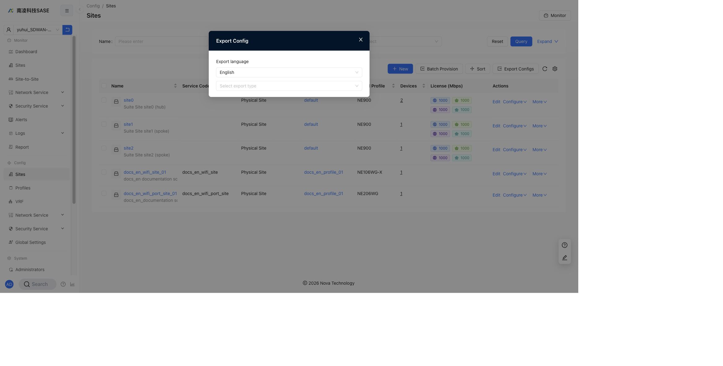
Export Configs
Click Export Configs to export site configuration.
The export dialog contains:
Export language: the current English UI showsEnglish.Select export type: choose the configuration type to export.
The export types are grouped by feature area. The dropdown shows options such as Business Policy, Transport QoS, ACL Firewall, Static Routes, and Policy Routes. Scroll the dropdown to view additional types such as TCP Optimization.
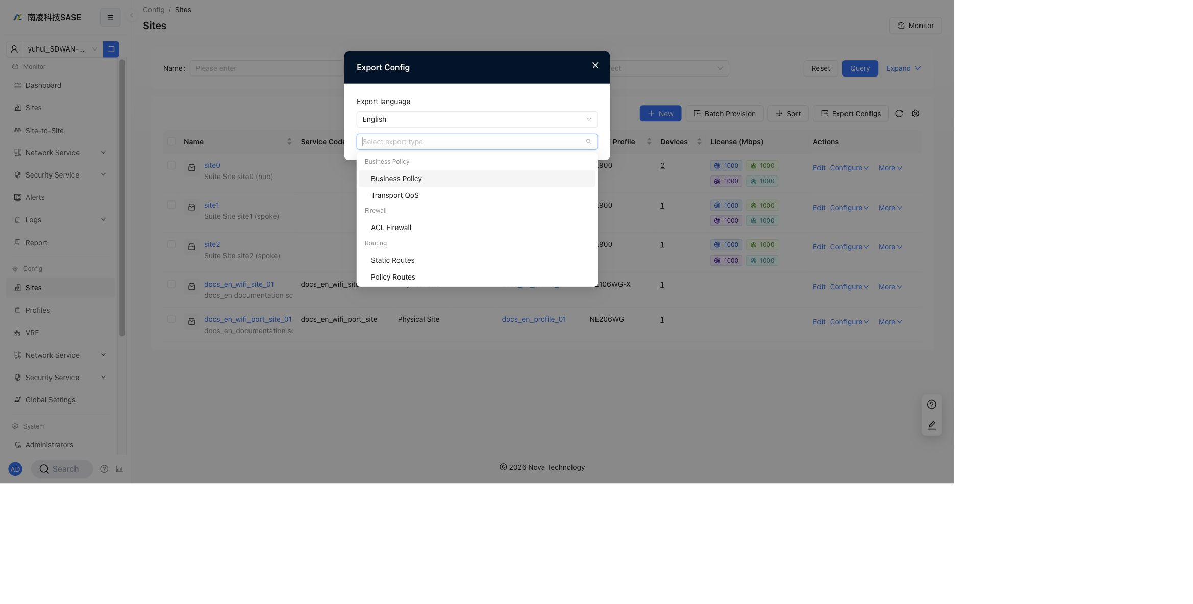
Export notes:
- Exported data is generated for site configuration review and offline troubleshooting.
- The export language follows the
Export languagefield in the dialog. - Select the export type according to the configuration area you need to audit, such as business policy, QoS, firewall, routing, or TCP optimization.
- If an export type has no configuration on the selected site, the exported file may contain an empty sheet or no effective rows for that feature.
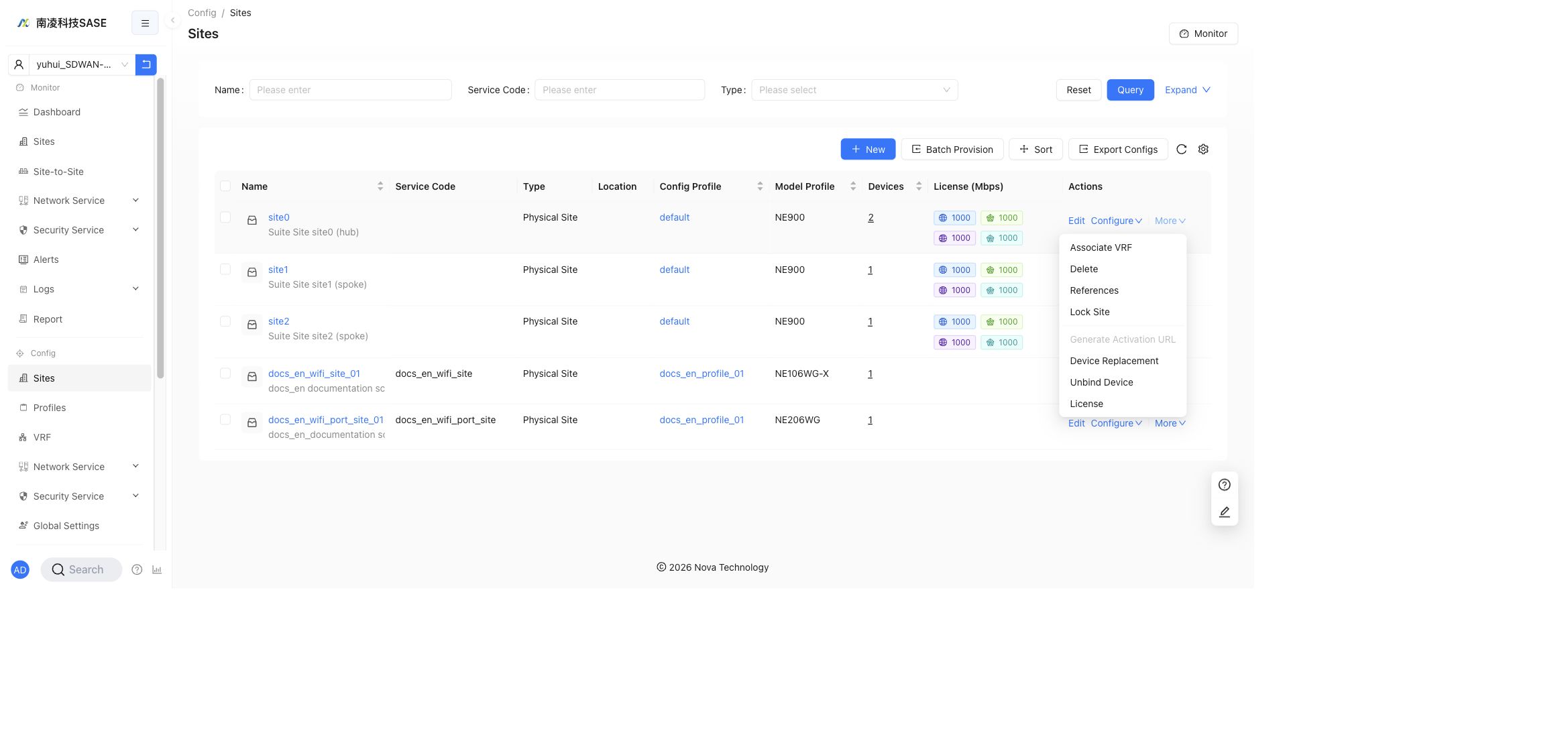
More Actions
Click More in a site row to open additional site actions.
The current menu contains:
Associate VRFDeleteReferencesLock SiteGenerate Activation URLDevice ReplacementUnbind DeviceLicense
Generate Activation URL may be disabled for an already activated site.
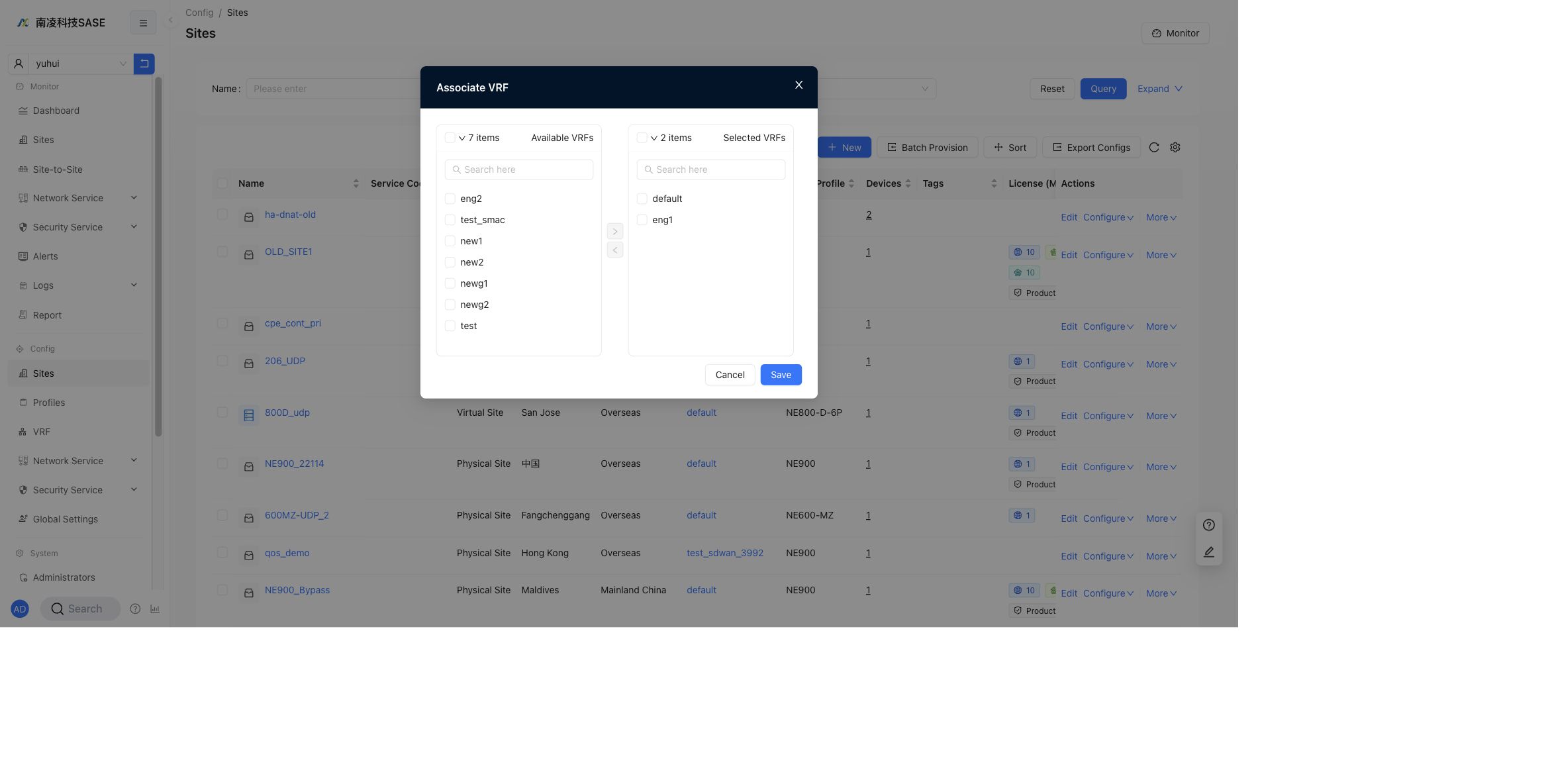
Associate VRF
Use Associate VRF to move VRFs between Available VRFs and Selected VRFs, then click Save.
Delete
Use Delete to remove a site.
Warning:
- Deleting a site cannot be restored.
- Confirm that the site is not still in use before deletion.
- If the site has device bindings, policies, or referenced configuration, check
Referencesfirst.
References
Use References to check whether the site is referenced by other configurations. If the site is not referenced, the page shows a success message.
Lock Site
Use Lock Site to prevent accidental changes.
After a site is locked:
- It cannot be edited.
- It cannot be configured.
- It cannot be deleted.
- Use the unlock action from
Morebefore making changes again.
Generate Activation URL
Use Generate Activation URL to generate the activation URL used during NSE installation and initialization.
This action can be disabled when the selected site or device state does not require a new activation URL.
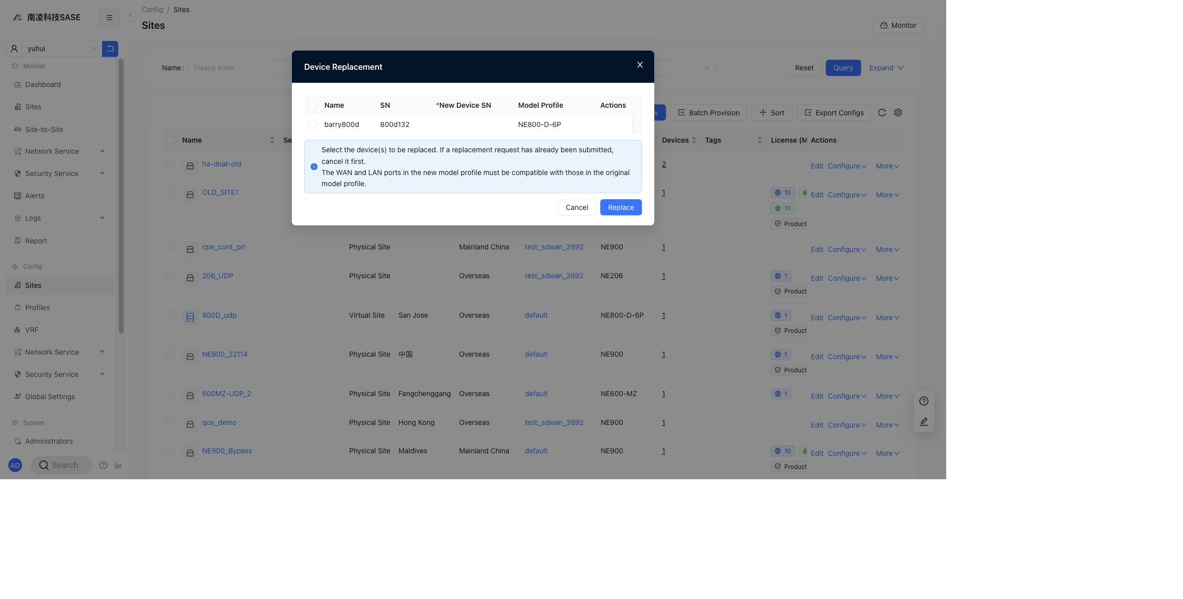
Device Replacement
Use Device Replacement to replace one or more devices. Select the device, enter the new device SN, and confirm the replacement.
If a replacement request already exists, cancel it before submitting a new one. The WAN and LAN ports in the new model profile must be compatible with the original model profile.
Unbind Device
Use Unbind Device to detach a device from the site.
Warning:
- Unbinding a device clears the relationship between the device and the site.
- Device-side configuration may be cleared according to the unbind workflow.
- Confirm that the device is no longer carrying production traffic before unbinding it.
License
Use License to edit bandwidth and security license settings for the site.
The dialog contains:
Nova Internet bandwidth (Mbps)Nova private bandwidth (Mbps)Hub-Spoke Internet bandwidth (Mbps)Hub-Spoke private bandwidth (Mbps)Enable security license
If Nova private bandwidth is empty, the limit is 1 Kbps. If Hub-Spoke Internet or Hub-Spoke private bandwidth is empty, there is no limit. When both Nova Internet and Nova private exist, Internet can share private bandwidth.
