Nova Gateways
Nova Gateway connection
"Tenant" → "Config" → "Network Service" → "Nova Gateways" → "Nova Gateway Connection" → [New]
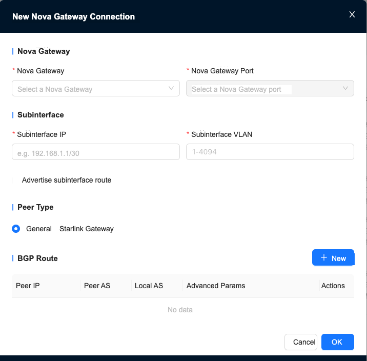
The Nova Gateway port can only be selected after selecting a Nova Gateway, and the selected Nova Gateway must have an NNI port.
Peer type: Universal mainly includes sites, data centers, etc. Xinglian is Nanling Technology’s zero-trust access gateway.
BGP routing
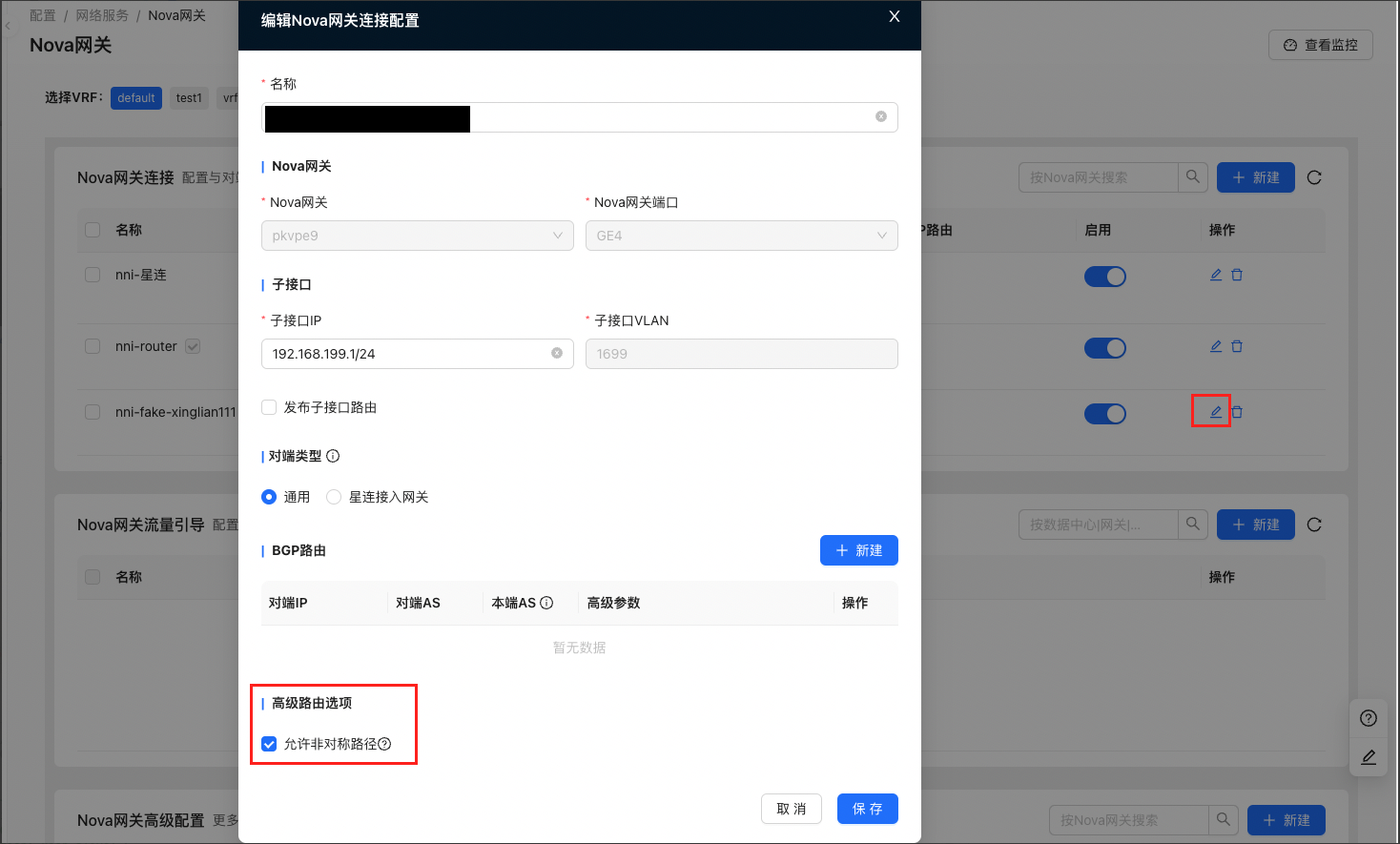
[New Nova Gateway Connection Configuration] → [New]
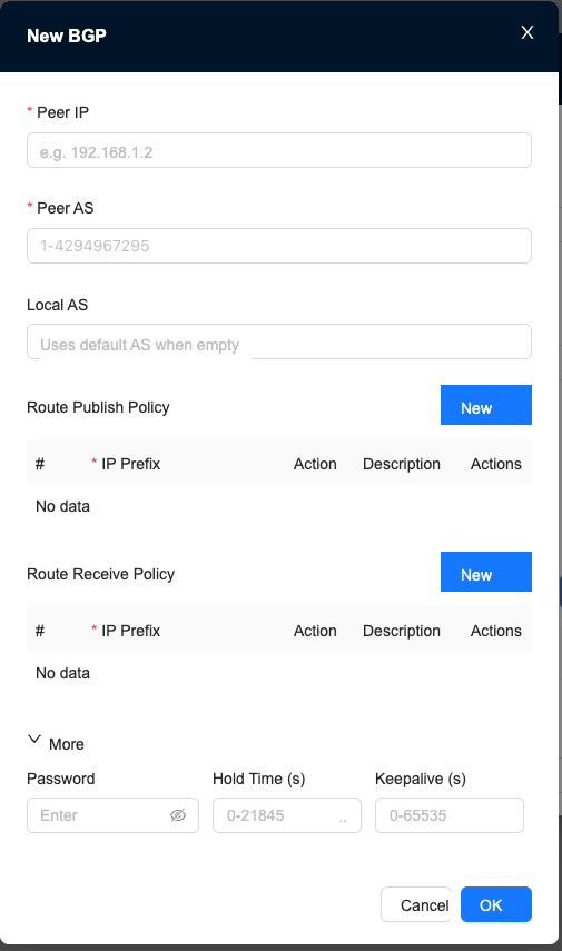
- If the local AS is not filled in, the default value 4290000006 will be used.
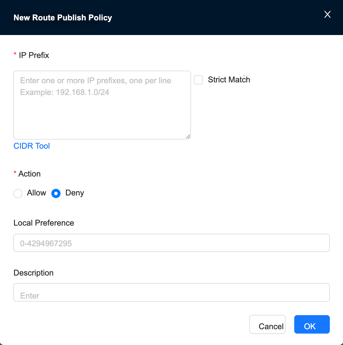
- Route publishing policy: When exchanging routes with the peer using BGP, control the routing information published by this gateway.
- Route reception policy: When exchanging routes with the peer using BGP, control the routing information received by this gateway.
Route publishing/receiving strategy
Advanced routing options
Asymmetric Path
Nova Gateway traffic guidance
Create a new traffic guidance configuration
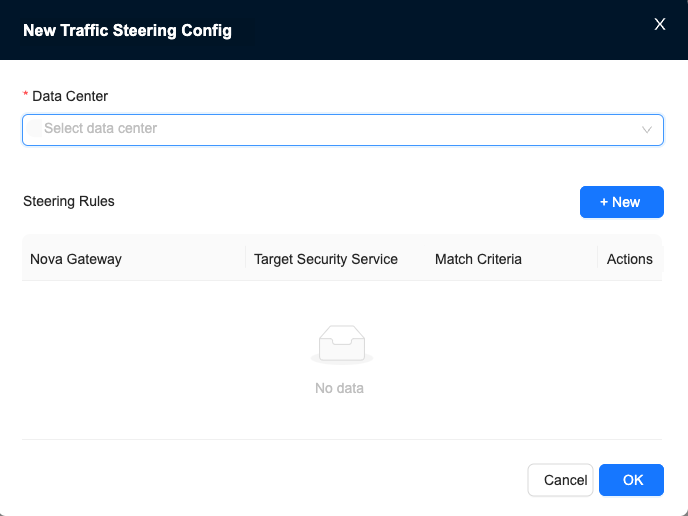
You need to set up the data center and select the data center before configuring traffic diversion rules.
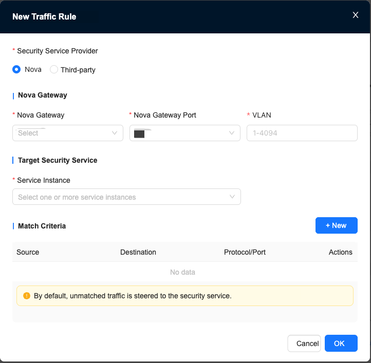
Create new traffic rules
The selected Nova Gateway must contain a traffic diversion port.
Target Security Service: When selecting multiple service instances, the first security instance is the primary one, and the rest are backup
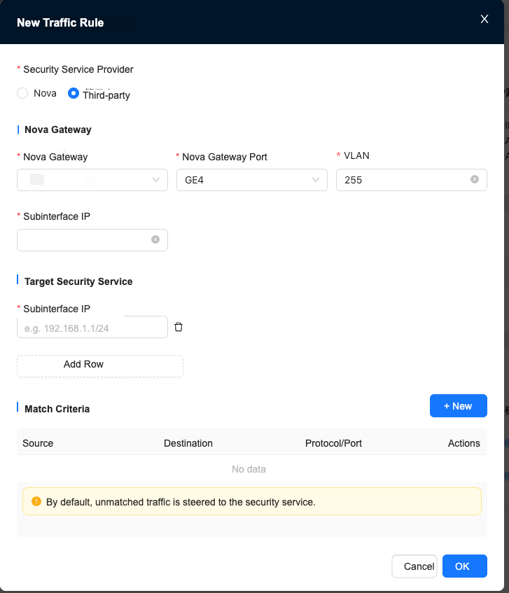
The Security Service provider of traffic diversion rules needs to provide the following sub-interface IP when selecting a third party:
The sub-interface IP of Nova Gateway and Security Service
The IP address of the sub-interface connecting the security instance to the gateway (if multiple entries are entered, the first security instance will be the primary one, and the rest will be backup)
If no matching conditions are set, all traffic will be directed to the Security Service. After the matching conditions are established, traffic that meets the conditions will be directed to the Security Service.
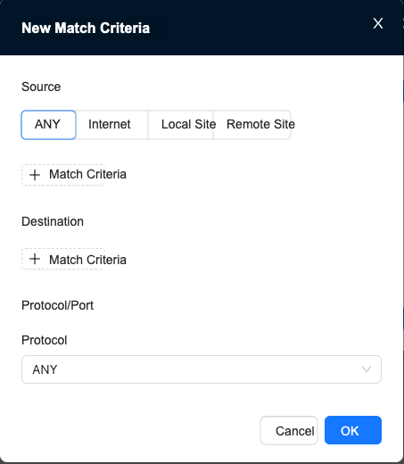
Create new matching conditions
When selecting TCP or UDP protocol, you need to set the source port and destination port, which can be left blank.
Nova Gateway advanced configuration
The advanced configuration process of Nova Gateway is as follows:
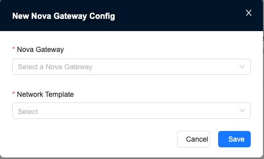
- Click New
- Select a Nova Gateway and click OK to create an empty gateway configuration, as shown in Figure 1
Need to match related Network Profiles
- Edit the empty gateway configuration, as shown in Figure 2
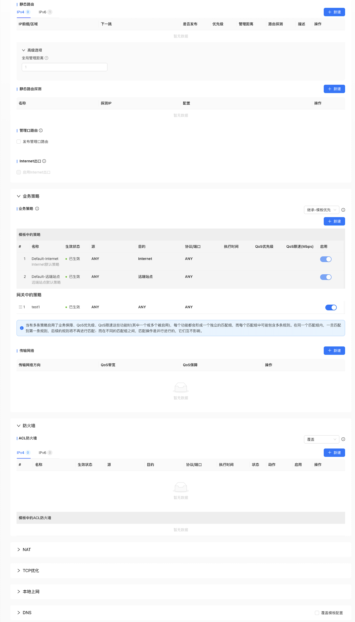
The following will introduce each function from top to bottom.
Routing
You can choose to configure static routing and Policy Routing, and you can also publish management port routes.
Static routing
The new static routing interface is shown in Figure 4
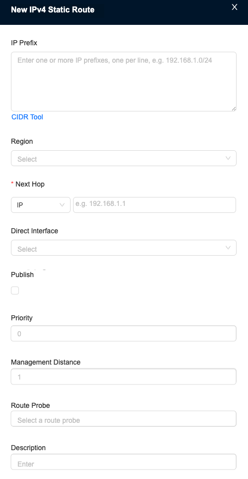
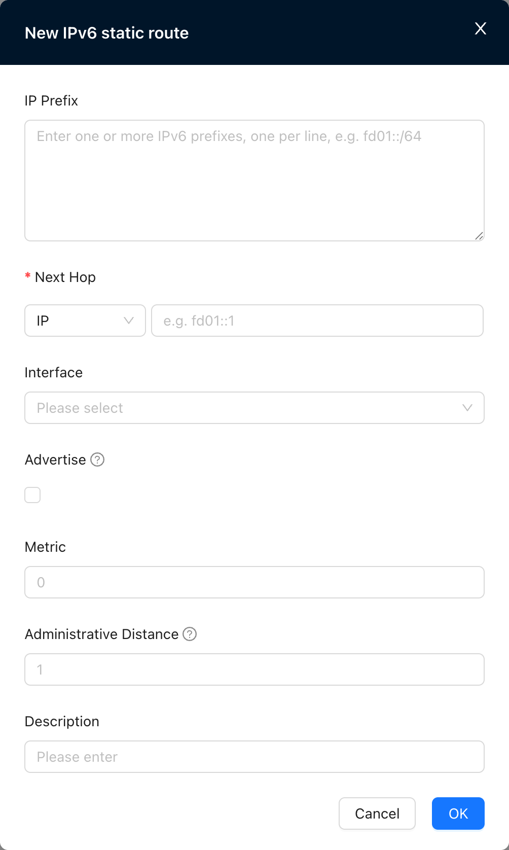
The following options are available for the next hop:
- IP, you need to fill in the next hop IP
- Other VRFs, VRF needs to be created
- WAN
- 远端站点
- Black Hole After checking whether to publish, the static route can be published to other sites. Static route priority: the metric value of the route. For routes of the same protocol, the greater the metric value, the lower the priority. Static routing management distance: the priority of the routing protocol, usually a number between 0 and 255. The larger the number, the lower the priority.
Policy Routing
The new Policy Routing interface is shown in Figure 5.
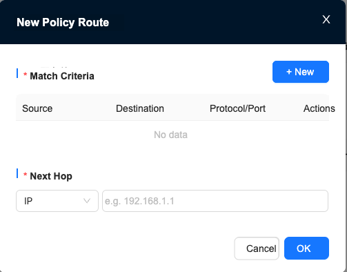
Matching conditions can be set and edited, and new matching conditions can be created as shown in Figure 6.
Optional match source type.
After clicking the matching condition, you can directly match the IP or set an Address Group.
The Address Group is located at "Tenant"→"Config"→"Network Service"→"Network Objects"→"Address Group"
Address groups can be created or edited here.
If you choose TCP or UDP as the protocol, you can choose to fill in the port.
Management port routing
After the management port route is published, the IP can be used as the gateway's DNS server IP or used for speed testing. When used as a DNS server IP, the CPE or Starlink access gateway connected to the gateway can hand over its DNS resolution request to the gateway for processing.
Internet exit
After the Internet egress is enabled, the CPE connected to the gateway will use the gateway as its Internet egress.
Business Policy
- Source and destination do not support selecting "Internet-Internet" or "Remote Site-Remote Site"
- When either source or destination is ANY, it will not take effect on "Internet-Internet" and "Remote site-Remote site" traffic.
- Supports configuring source host speed limit when the source is this site
- Supports configuring destination host speed limit when the destination is this site
Create a new Business Policy
Create a new Business Policy table as shown in Figure 7
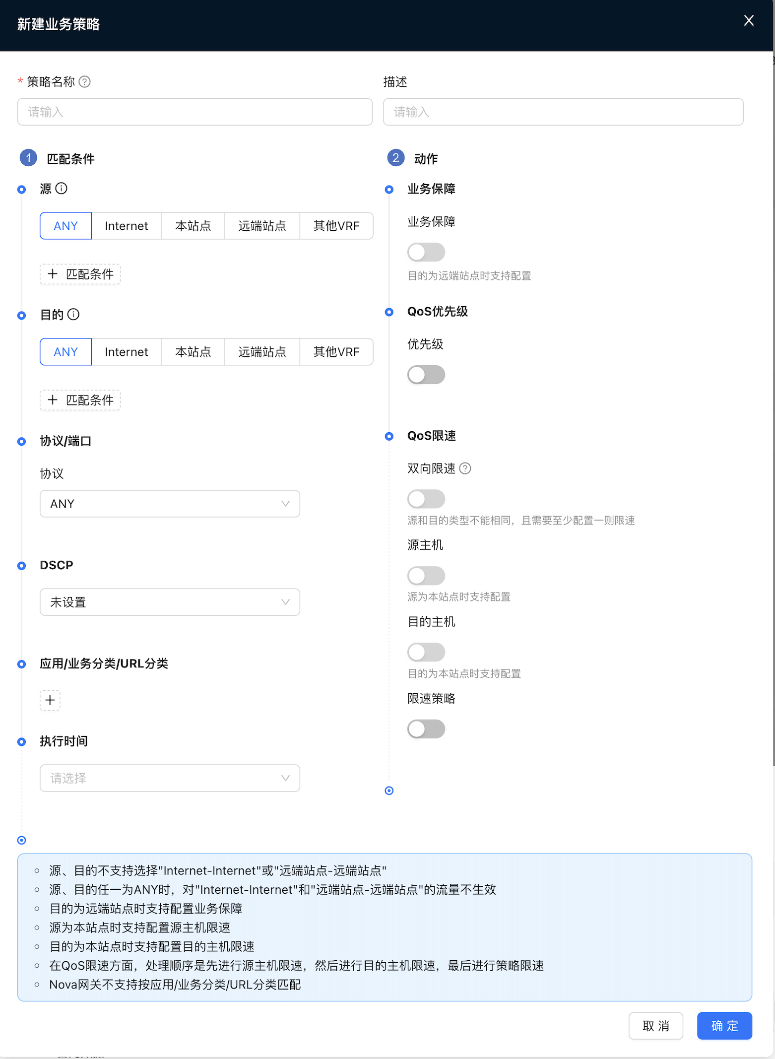
- Open the priority, you can choose default, gold, silver or bronze as the priority.
- Turn on policy speed limit, and you can choose to limit the bandwidth, up to 100000Mbps
- Supports configuring the source host speed limit when the source is the host site.
- Supports configuring destination host speed limit when the destination host is this site
Traffic label strategy
The traffic label policy supports classifying traffic based on L3/L4 matching conditions (source/destination IP, protocol/port, DSCP) and labeling it with a preset "traffic label". These tags can later be used for more refined business scheduling or policies.
In the New Traffic Label Policy dialog box, configure the following information and click OK
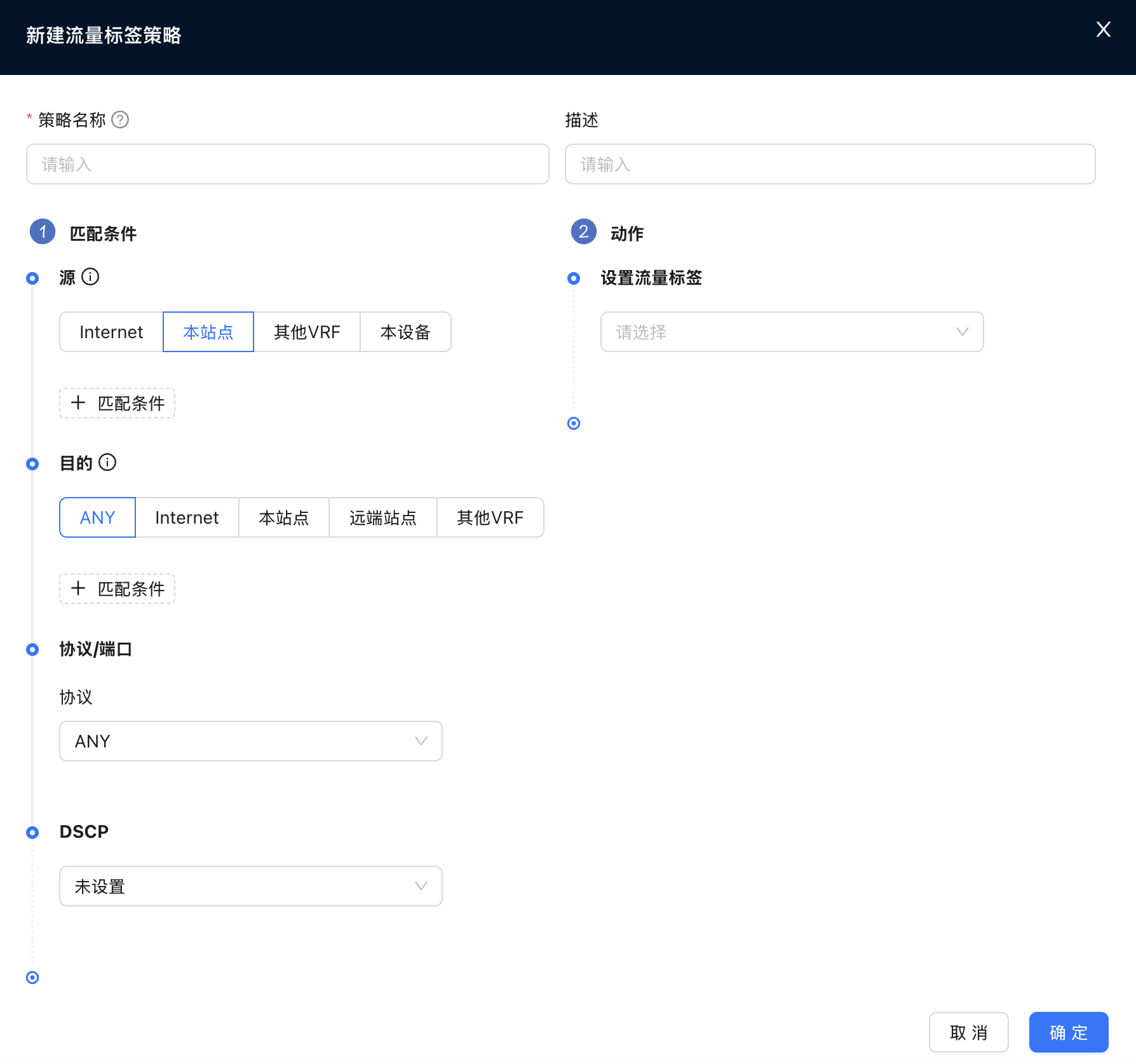
- Policy Name: Configure the name of the policy.
- Description: Configuration policy description information (optional).
- Matching conditions:
- Source/Destination: Supports quick selection by Internet, this site, remote site, other VRF, this device, etc., and also supports manual addition of specific IP prefixes.
- Protocol/Port: Supports ANY, TCP, UDP, ICMP. When selecting TCP/UDP, you can specify the source port and destination port.
- DSCP: Match the DSCP mark in the packet.
- Action:
- Set Traffic Label: Select the traffic label to be applied to the matching traffic.
Firewall
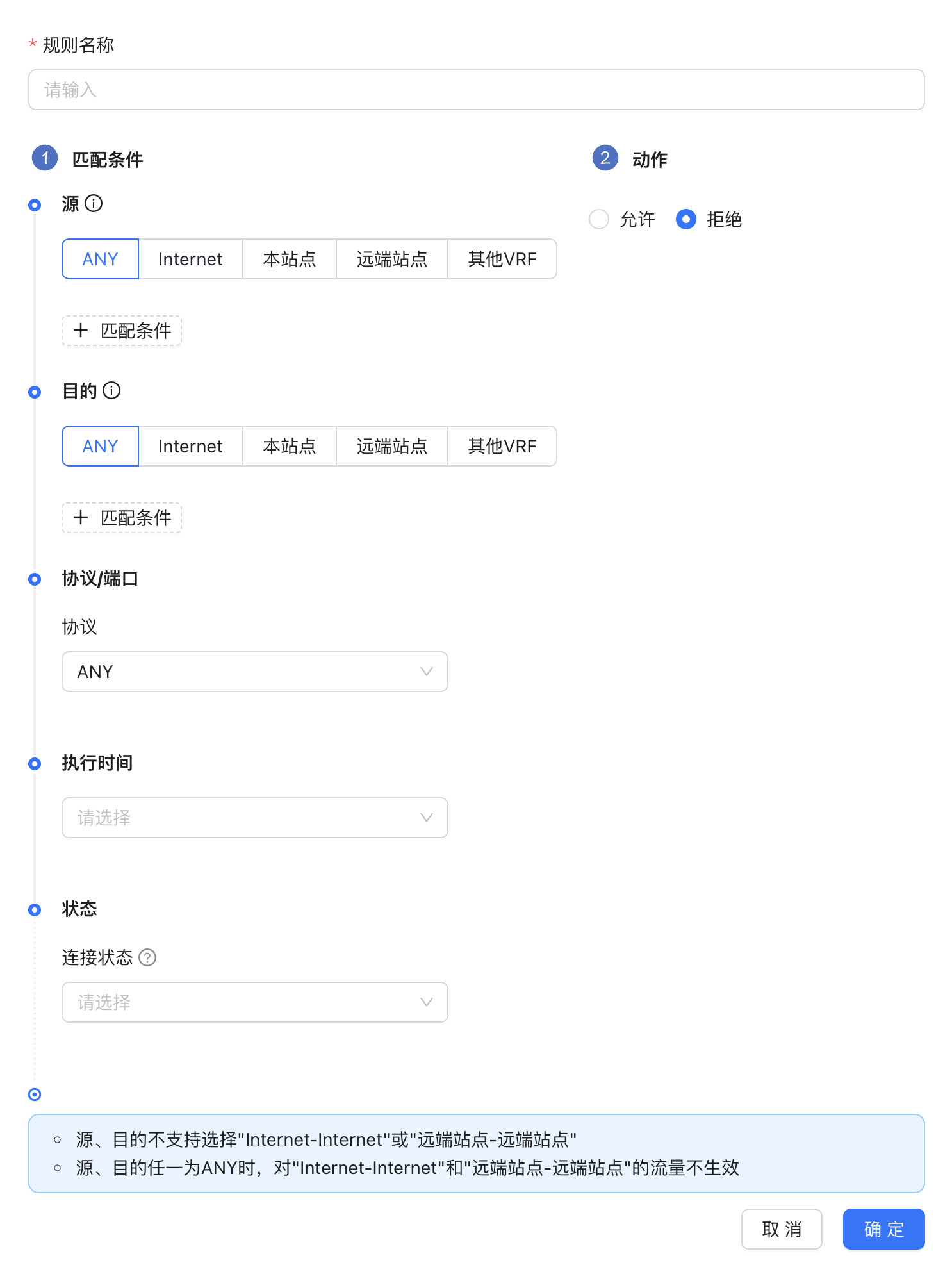
- Source and destination do not support selecting "Internet-Internet" or "Remote Site-Remote Site"
- When either source or destination is ANY, it will not take effect on "Internet-Internet" and "Remote site-Remote site" traffic.
Create new firewall rules
The new firewall rule form is shown in Figure 8
NAT
This item can configure DNAT and SNAT.
DNAT: Used to configure the DNAT function, which can map [IP/network segment, protocol, port before conversion] to [IP/network segment, protocol, port after conversion]. The external network can access the internal network through the mapped address, so that the internal network can provide services to the outside world.
SNAT:Used to configure the SNAT function, which can map [IP/network segment before conversion] to [IP/network segment after conversion]. The internal network can access the external network through the mapped address, but the external network cannot actively initiate access to the internal network through the mapped address
DNAT
The new DNAT rule form is shown in Figure 9
- If IP port conversion is performed, the IP before conversion and the IP after conversion will be one-to-many or one-to-one.
- If IP network segment conversion is performed, the IP network segment before conversion and the IP network segment after conversion will be one-to-one. If fixed. No port conversion
- The DNAT address pool is added to the IP address pool in ["Tenant"→"Config"→"Sites"→"Config"→"Global"→"WAN"→"IP Address Pool"] (/tenant/config-site#ip-address-pool)
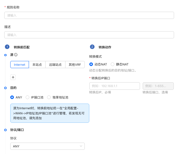
SNAT
The new SNAT rule form is shown in Figure 10
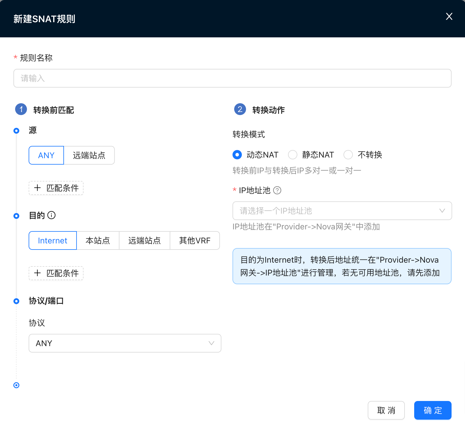
- Source supports matching sites
- If IP port conversion is performed, the IP before conversion and the IP after conversion will be one-to-many or one-to-one.
- If IP network segment conversion is performed, the IP network segment before conversion and the IP network segment after conversion will be one-to-one. If fixed. Ports are not translated.
- If you choose a shared address pool, randomly select one from the address pool as the converted address.
- If you choose the VRF exclusive address pool, you need to fill in a converted address, which must be within the selected address pool range.
- If not converted, the IP address before conversion will not be converted.
- When the destination is the Internet, the addresses before conversion are managed in [Provider -> Resource -> Gateways -> IP Address Pool/IP Port Pool] (/provider/resources#ip-address-pool). If there is no available address pool, please add it first
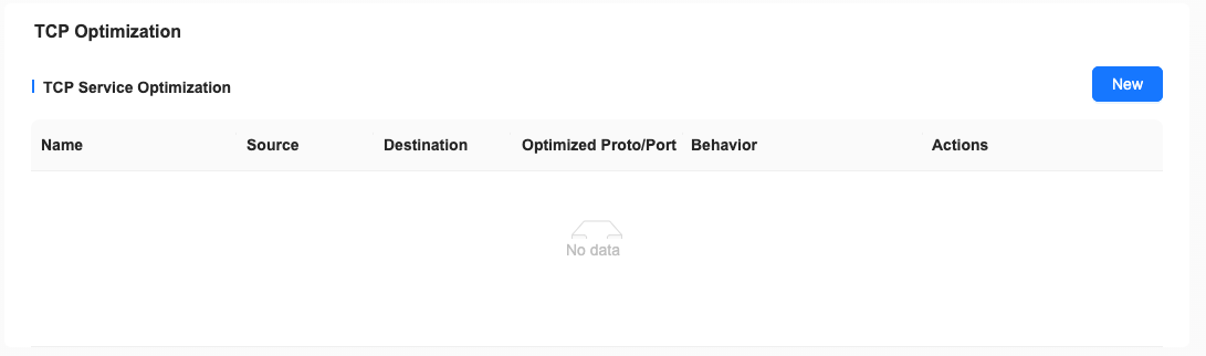
TCP optimization
When the end-to-end delay of the SDWAN link is large (>20ms) and the link quality is poor, the bandwidth of a single TCP Flow cannot be increased (especially Windows terminals). You can configure the TCP optimization function for the specified service to increase the transmission rate. Devices configured with TCP optimization should be as close as possible to the data sender, such as:
- Downloading large files from the App Acceleration exit should be configured on the NSS device;
- To upload large files, CPE should be configured on the access side;
Local Internet access
Local Internet access as shown in Figure 11
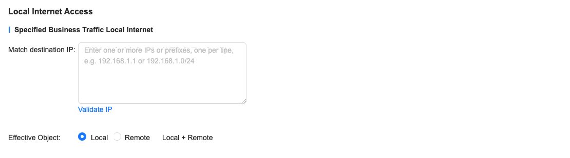
Since there are many destination IPs, it is unclear whether the new IP is already among the destination IPs. Therefore, you can click Verify IP to verify whether the newly added IP is already in the destination IP table.
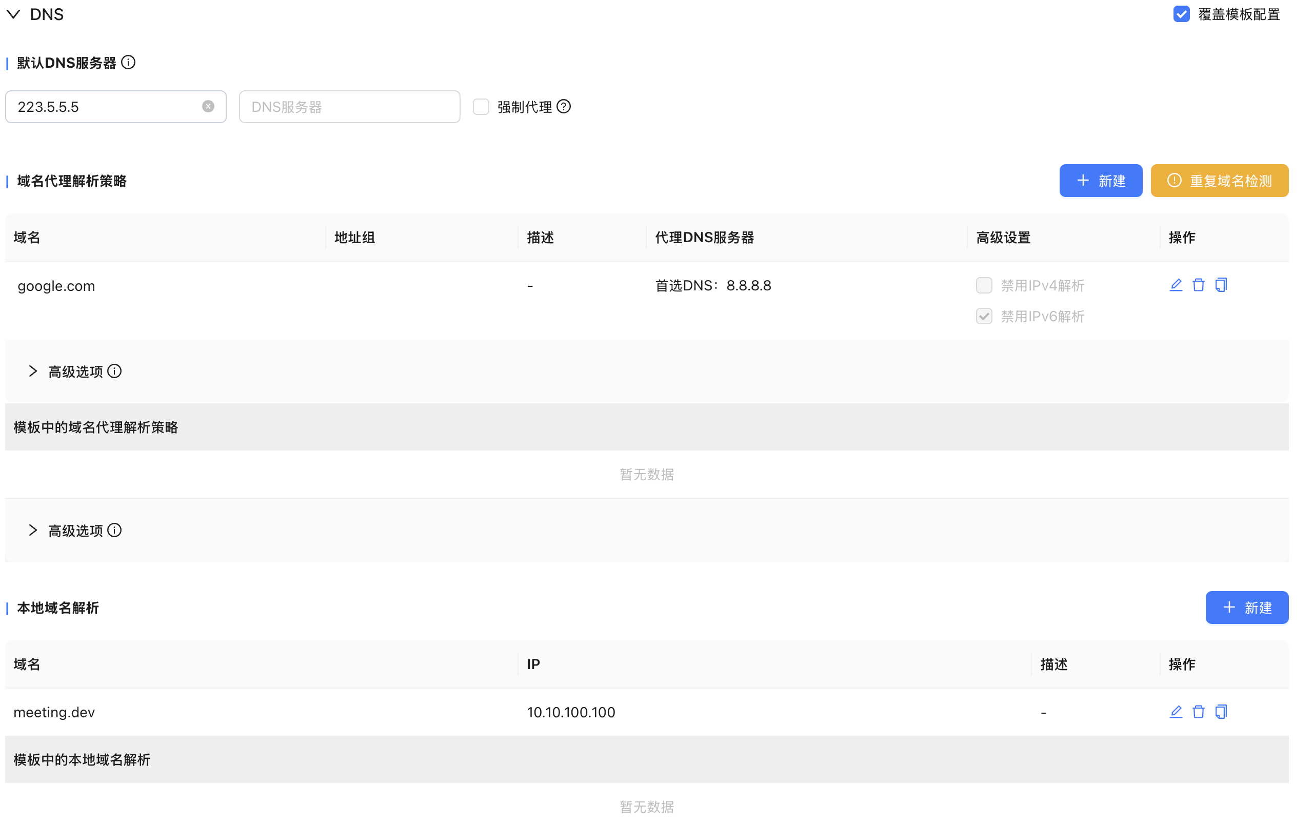
DNS
DNS configuration is as shown in Figure 12, you can choose to force proxy
Nova Gateway high availability group configuration
Achieve gateway high availability and ensure business reliability through active and backup configurations
Reference and configure the gateway group
"Tenant"→"Config"→"Network Service"→"Nova Gateways"
- Click New
- Select a Nova Gateway high availability group
- Select a Network Profile
- Configure the address pool
- You can customize the main and backup gateways optional
Instructions for tenants to reference high-availability gateway groups
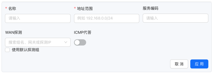
Illustration 1
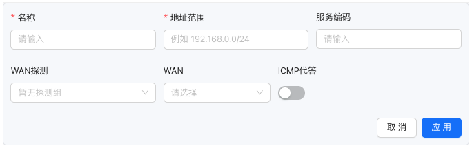
Illustration 2
- The active and standby relationships within the high-availability gateway group support custom configuration
- A single tenant can reference multiple high-availability gateway groups at the same time
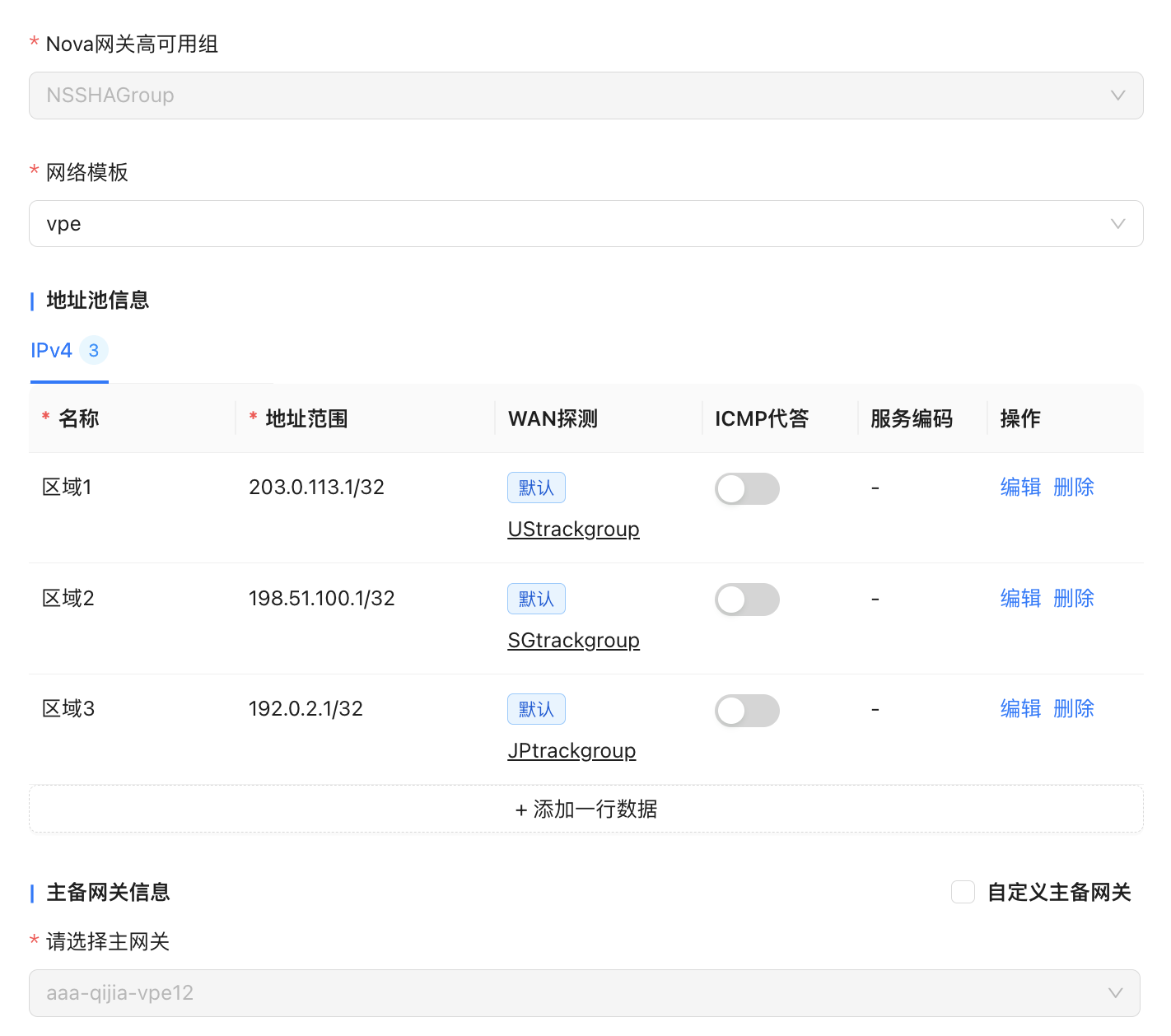
- When the gateway has been configured with a global WAN address pool, the default detection group can be used without specifying the WAN interface, as shown in Figure 1; when the gateway is not configured with a global WAN address pool, the address pool entry can specify the WAN interface separately, as shown in Figure 2
- Address pool entries support manually specifying detection groups
- The address range of the address pool entry must be included in the global address pool range
- The address range of the address pool entry cannot overlap with the address range in this policy or other VRF/tenant policies
SNAT policy traffic label
"Tenant"→"Config"→"Network Service"→"Nova Gateways"→"Edit Nova Gateway Group Configuration"→"NAT"
SNAT policy and detection group linkage
"Tenant"→"Config"→"Network Service"→"Nova Gateways"→"Edit Nova Gateway Group Configuration"→"NAT"
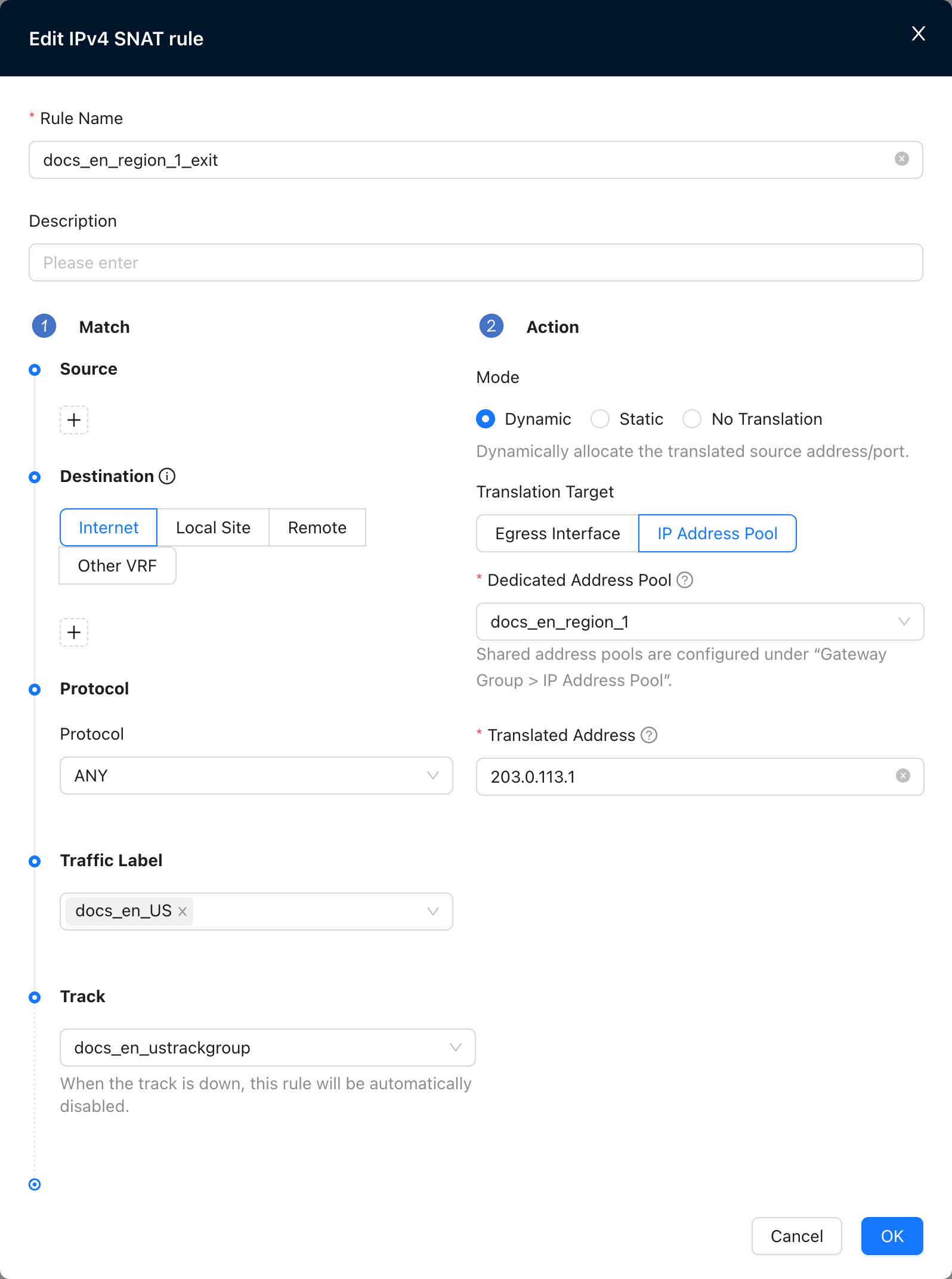
- When the associated detection fails, the SNAT policy automatically expires and traffic will continue to match subsequent policies
Configuration example
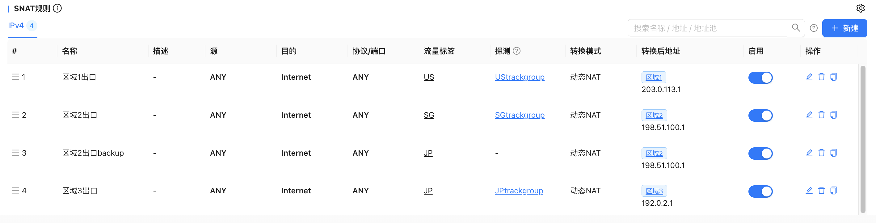
Configure tenant high-availability gateway address pools by region
Tenant site traffic matches the corresponding SNAT rule based on the traffic label (US/SG/JP) and is sent to the designated exit by the gateway. When the detection of the main exit fails (such as the area 3 exit), the traffic is automatically switched to the backup exit (such as the area 2 exit) for outgoing traffic, realizing a seamless switch between the main and backup exits.
Enable traffic collection
"Tenant"→"Config"→"Network Service"→"Nova Gateways"→"Edit Nova Gateway Group Configuration"→"Function Management"
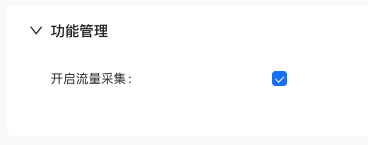
- Historical traffic before the function is enabled will not be counted
- Only count egress IP traffic after SNAT
- Highly available gateway monitoring📖