AWS HA Deployment plan
1. Program background
The business needs to deploy two NE900 (active/standby) on AWS to realize networking with other sites and achieve active and standby redundancy.
Traditional VRRP cannot be deployed because AWS is not supported
Using AWS Transit Gateway (TGW) + BGP redundant scheme
Establish BGP between the LAN side of the active and standby devices and TGW. The LAN side controls the priority of the active and standby devices through the AS_PATH length, and Transmission Networkcontrols the priority through the siteVRF route publishing priority.
2. Network architecture
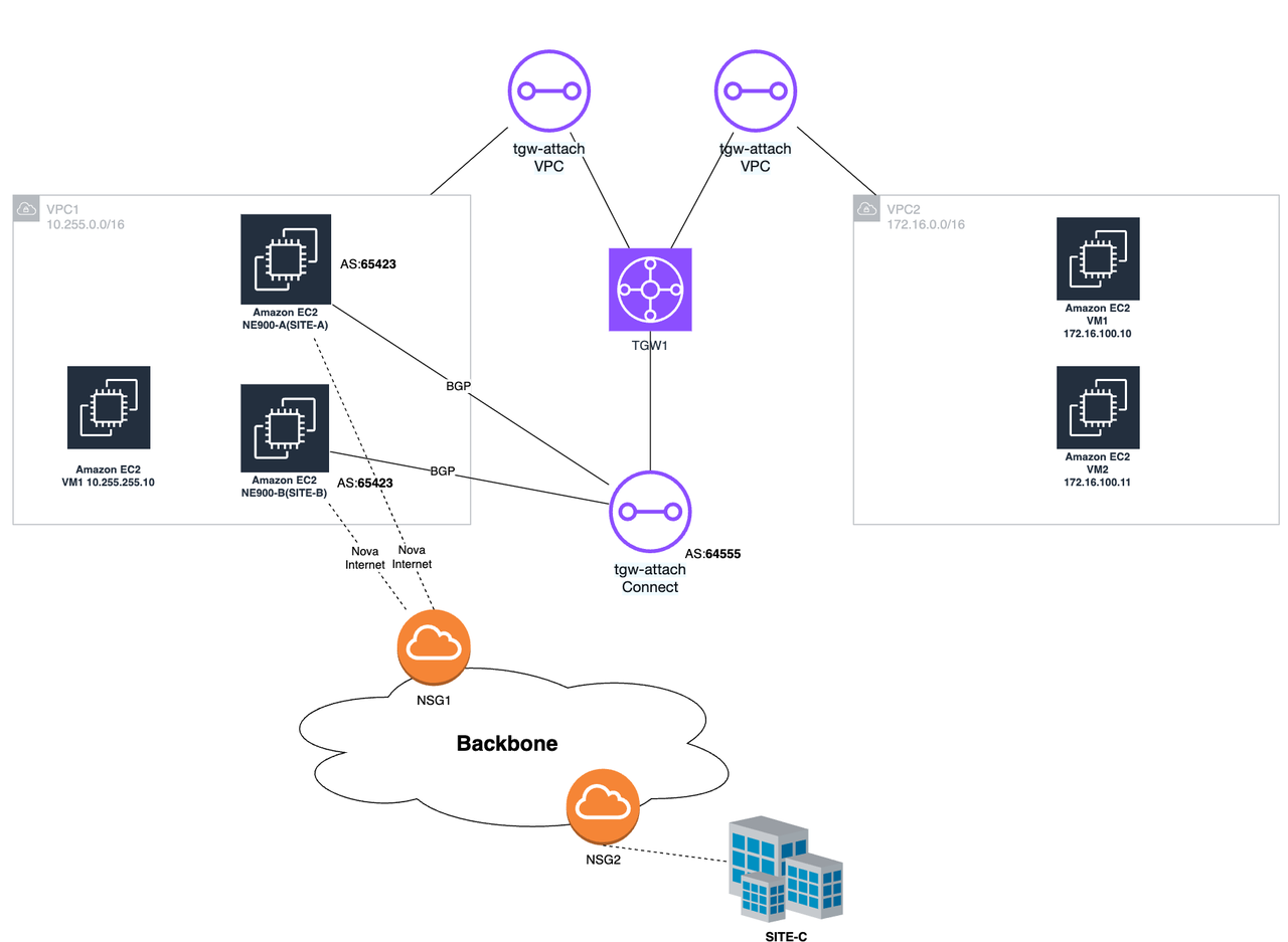
Topology Description:
Two NE900 are deployed on the same VPC and are bound to 2 sites respectively.
Configure gateways for two sites respectively
Each site establishes a BGP connection via the LAN side with TGW Attachment (Connect type)
The main site publishes BGP route AS_PATH short, standby device AS_PATH long- The primary site is set toVRF route publishing priority high, and the backup site is set to low
TGW forwards the traffic of service VPC to priority NE900 according to the routing policy
Description:
VPC1 is the VPC where NE900 is located, or it can be the customer's business VPC.
VPC2 is another business VPC of the customer (if the customer has multiple VPCs)
NE900-A is the primary VCPE and is used for site SITE-A; NE900-B is the backup VCPE and is used for site SITE-B.
SITE-C is another non-AWS site of the customer, and the LAN side network segment is 192.168.100.0/24
3. Configuration process
Configuration background: Take the above topology as an example for configuration; the customer already has VPC1 (10.255.0.0/16) and VPC2 (172.16.0.0/16)
SITE-A: Primary site, bound to device NE900-A
SITE-B: Standby site, bound to device NE900-B
SITE-C: Another site
Configuration target: VPC1 and VPC2 can communicate with SITE-C
3.1 AWS end-NE900 configuration
1. Create subnet
Create 3 subnets under the existing VPC1 (10.255.0.0/16), one subnet for wan and two for lan
subnet-wan: 10.255.255.0/24
subnet-lan: 10.255.200.0/24
subnet-lan-2: 10.255.201.0/24

If the customer needs multiple WAN exits, then multiple WAN subnets need to be created. For example, if 2 exits are needed, then 2 subnets are created. At the same time, please pay attention to the number of network cards supported by EC2 that is enabled.
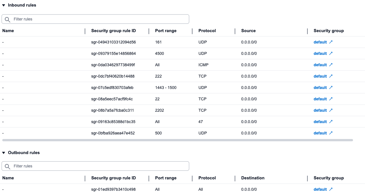
2. Configure security groups
Create or modify security group default and add inbound rules
- Release the protocols and ports as shown in the figure below
3. Create an EC2 instance
Create 2 EC2 (2C4G) and use NE900 image to install VCPE
Configure 2C4G (medium specification, supports up to 3 network cards)
Image selection NE900 (upload to aws by yourself)
Use subnet-wan for subnet
Use default for security group
Select 30G hard drive
4. Add network interface
After successful creation, add a private network interface to each device
Enter the instance, select Network and Security-Network Interfaces, and create a network interface.
Select the previously created subnet-lan for the subnet.
The default interface type is ENA
Fill in the IPv4 address of the site LAN port.
SITE-A: 10.255.200.201
SITE-B: 10.255.201.202
Select the created network interface ENI, click Operation-Attach, and select the NE900 instance we created in VPC1
If there are multiple wans, continue to add interfaces in the same way as above
The network interface used by lan must be off for source/destination checks
5. Add interfaces to the system
Log in to the created NE900 device and execute the following command through the command line to add an interface.
config -u ports/GE2 -m put '{"ifname": "eth1", "name": "GE2"}'
If there are multiple wan interfaces, such as GE3, add them in the same way
config -u ports/GE3 -m put '{"ifname": "eth2", "name": "GE3"}'
- Another NE900 performs the same operation
3.2 AWS end-TGW configuration
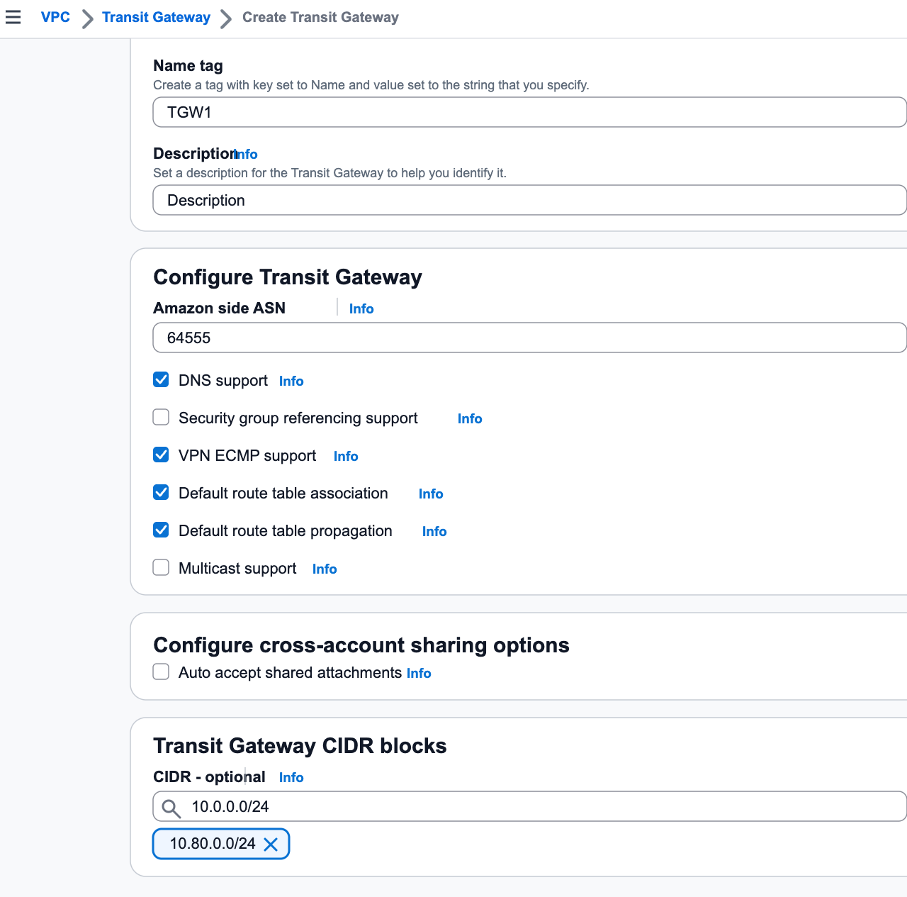
1. Create TGW
Configure asn: for example 64555
Configure Transit Gateway CIDR: for example 10.80.0.0/24
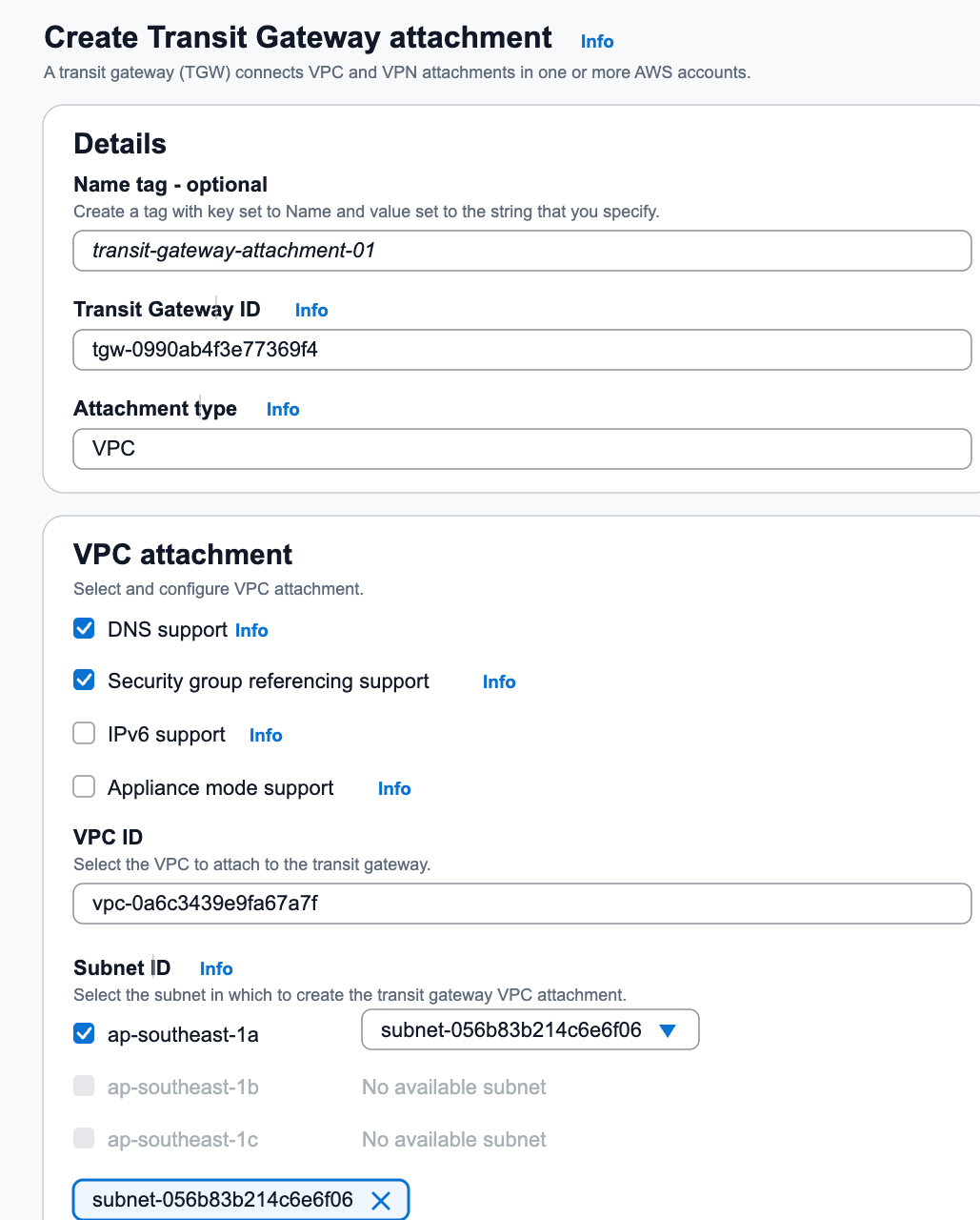
2. Create the TGW VPC Attachment of VPC1
Create TGW VPC Attachment (VPC mount) for VPC1 (the VPC where NE900 is located)1. Enter the transit gateway-transit gateway connection,Create Transit Gateway mount**
Select the tgw created previously
Mount type selection VPC
VPC mounting, select VPC1 (10.255.0.0/16)
Select the previously created subnet-wan for the subnet (this subnet is used to store the ENI of TGW)
If the VPC has multiple Availability Zones, you must select a subnet for each Availability Zone, otherwise the traffic across the Availability Zones will be blocked.
3. Create TGW VPC Attachment of VPC2
Create TGW VPC Attachment (VPC mount) for VPC2 (172.16.0.0/16, another customer VPC)
Enter the transit gateway-transit gateway connection, Create Transit Gateway mount
Select the tgw created previously
Mount type selection VPC
VPC mount, select VPC2 (172.16.0.0/16)
Select any subnet for subnet
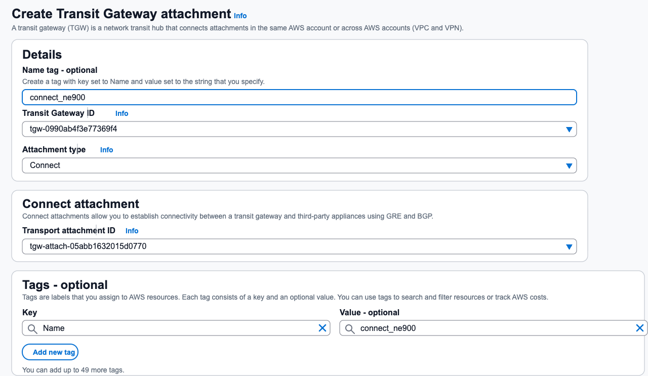
4. Create TGW Connect Attachment
Enter the transit gateway-transit gateway connection, Create Transit Gateway mount
Select the tgw created previously
Select mount type Connect
For the transmission attachment ID, select the tgw-attach id that just mounted VPC1.
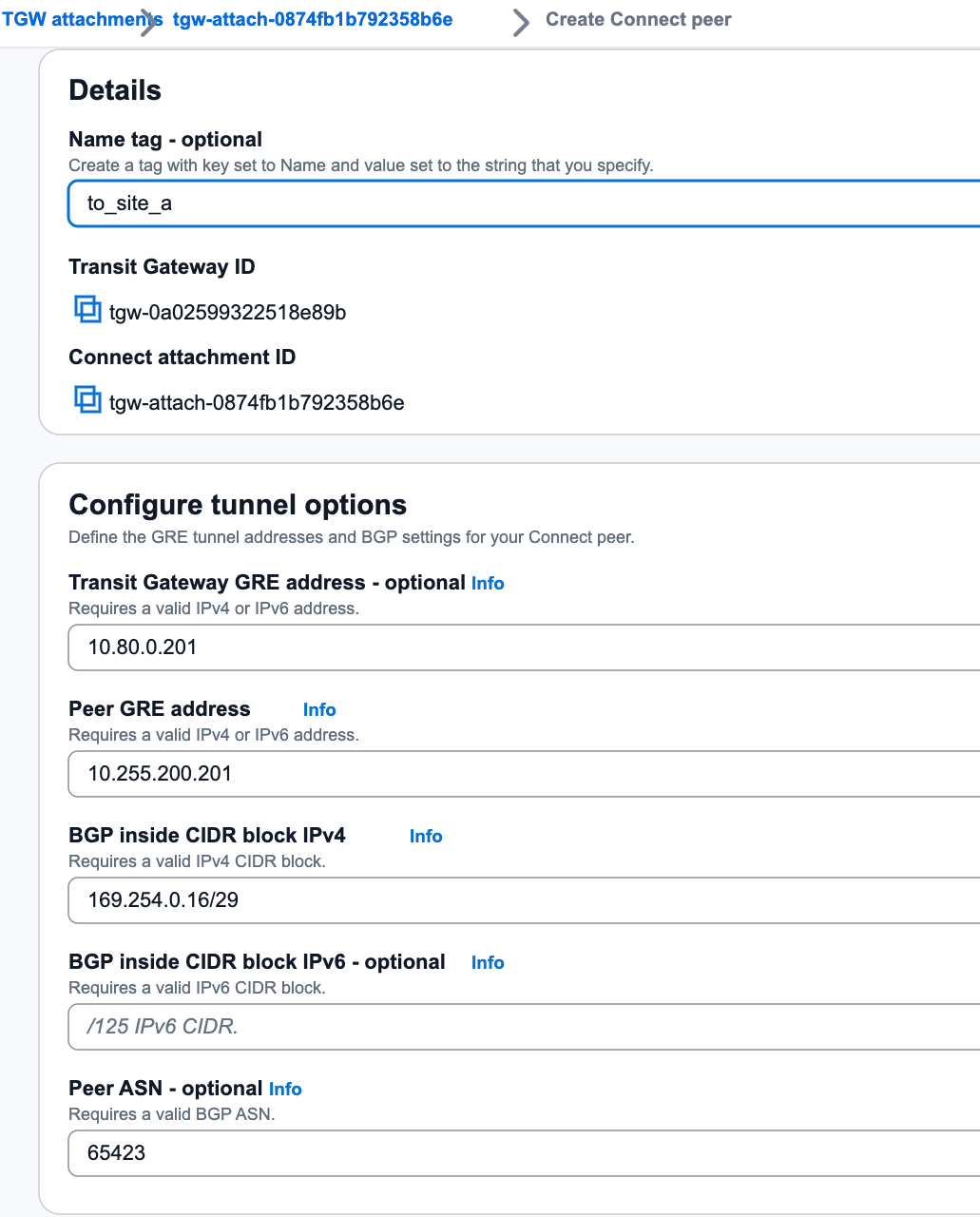
5. Create Connect peer (NE900-A)
Create Connect Peer (NE900-A)onTGW Connect Attachment
Reference: Connect attachments and Connect peers
- In Transit Gateway - Transit Gateway Mount, select the Connet mount you just created, and then click Create Connect Peering
- Transit Gateway GRE address: assign one in Transit Gateway CIDR, such as 10.80.0.2013. Peer GRE address: NE900-A’s lan address10.255.200.2014. BGP in CIDR block IPv4:169.254.0.16/29
The inside IP addresses that are used for BGP peering. You must specify a /29 CIDR block from the 169.254.0.0/16 range for IPv4. The following CIDR blocks are reserved and cannot be used:
- 169.254.0.0/29
- 169.254.1.0/29
- 169.254.2.0/29
- 169.254.3.0/29
- 169.254.4.0/29
- 169.254.5.0/29
- 169.254.169.248/29
- Peer ASN: For example 65423
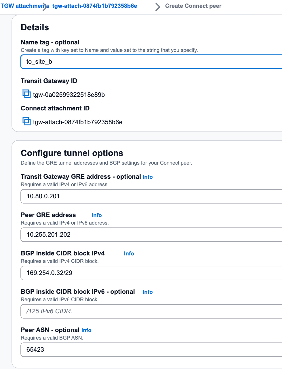
6. Create Connect peer (NE900-B)
Create Connect Peer (NE900-B)onTGW Connect Attachment1. In Transit Gateway - Transit Gateway Mount, select the Connet mount you just created, and then click CreateConnect Peering2. Transit Gateway GRE address: assign one in Transit Gateway CIDR, such as10.80.0.2023. Peer GRE address: NE900-B’s lan address10.255.201.2024. BGP in CIDR block IPv4:169.254.0.32/295. Peer-to-peer ASN: For example65423 (Note: the BGP AS of the two Connets must be consistent)
7. Configure VPC1 routing table - TGW CIDR
Add the route from Transit Gateway CIDRto TGW inVPC Route Tableof VPC1(10.255.0.0/16)The purpose of this route is to allow NE900 to access the TGW
Enter VPC-Routing Table-Routing-Edit Route-Add Route
The target is Transit Gateway CIDR, which is 10.80.0.0/24
The next hop is Transit Gateway, select the created tgw instance
8. Configure VPC1 routing table - private network segment
Add the route from private network segmentto TGW in theVPC Route Tableof VPC1 (10.255.0.0/16)The purpose of this route is to import the east-west traffic that needs to be accessed to the TGW
The target is the private network address 192.168.0.0/16; 10.0.0.0/8; 172.16.0.0/12
The next hop is Transit Gateway, select the created tgw instance
Fill in the fields as required. For example, if the remote plan is 10.0.0.0/16, fill in the fields as needed. If you are not sure, you can write the three major private network segments.
9. Configure VPC2 routing table
Add the route from private network segmentto TGW in theVPC Route Tableof VPC2 (172.16.0.0/16)The purpose of this route is for VPC to import traffic to TGW
The target is the private network address 192.168.0.0/16; 10.0.0.0/8; 172.16.0.0/12
The next hop is Transit Gateway, select the created tgw instance
Fill in the fields as required. For example, if the remote plan is 10.0.0.0/16, fill in the fields as needed. If you are not sure, you can write the three major private network segments.
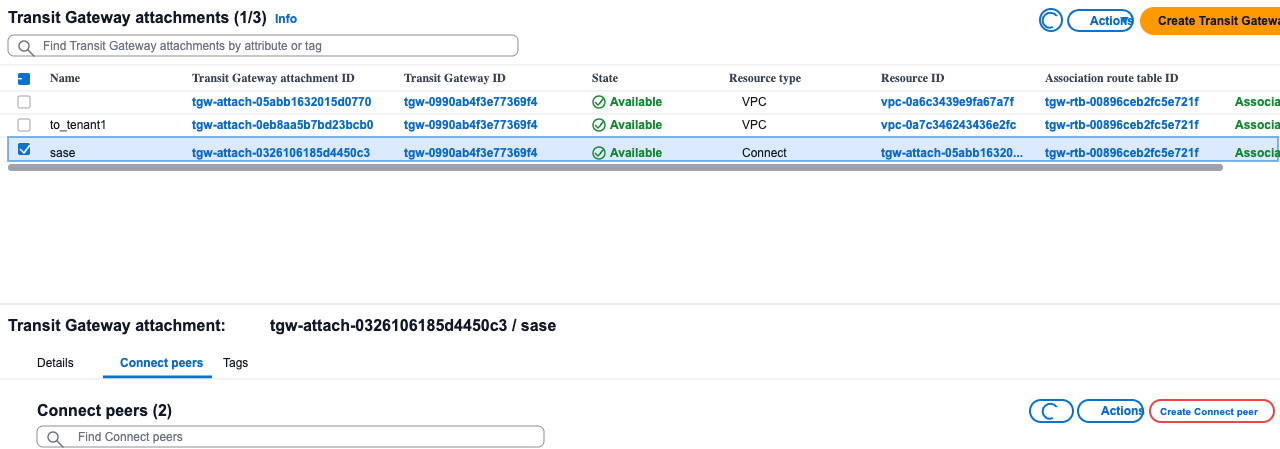
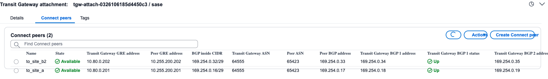
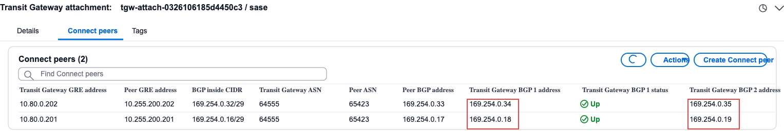
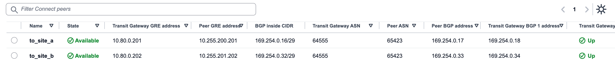
10. View Connect peer information
After the creation is completed, check the Connect peering information and obtain the Peer BGP address
3.3 SASE side configuration
1. Create a site
Create 2 sites and bind 2 NE900s
SITE-A NE900-A
SITE-B NE900-B
2. Configure WAN and LAN interfaces
Configure WAN and LAN interfaces at 2 sites respectively
WAN port configuration Nova Internet transmission network label (If it is a cloud dedicated line, change it to Nova dedicated line)
For the LAN port, select GE2 and configure the address (the address uses the previously mounted network card address)
SITE-A 10.255.200.201/24
SITE-B 10.255.201.202/24
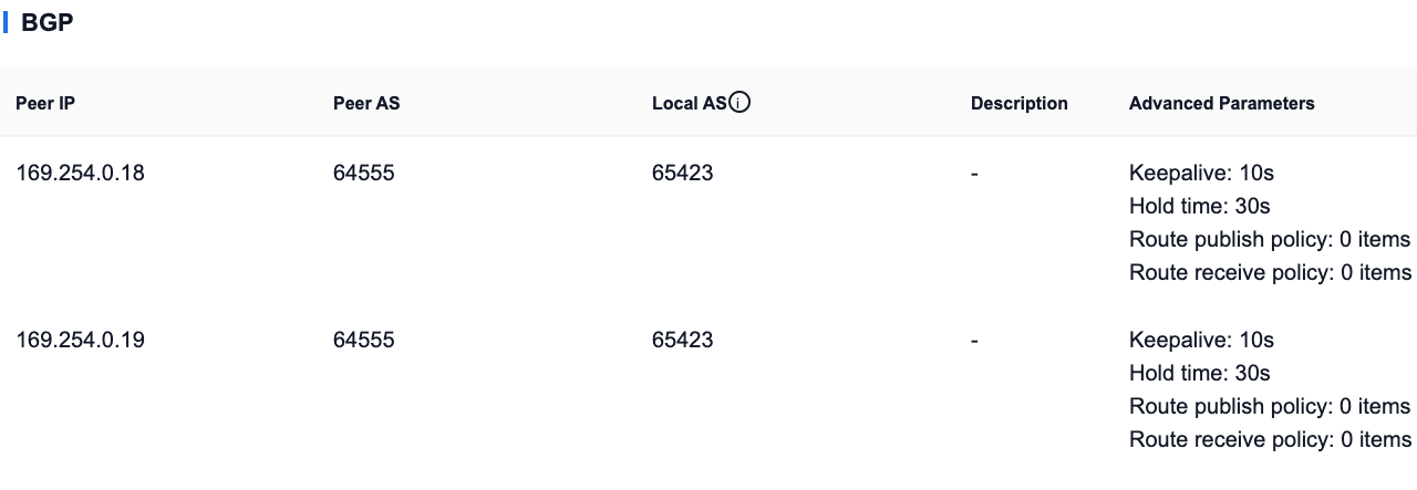
3. Configure BGP connection
The two sites are respectively configured with BGP connections to the TGW. For information, refer to the Connect peer information of the TGW (keep-alive 10 seconds hold timer 30 seconds)
Note: Each site must establish 2 BGP connections with the TGW.
Reference: https://docs.aws.amazon.com/vpc/latest/tgw/tgw-connect.html
SITE-A: Main site
AS Path Prepend Default 0
SITE-B: Standby site
AS Path Prepend length is 3
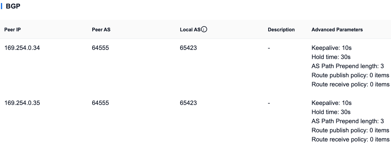
Note: TGW defaults to BGP keep-alive 10 seconds; Default hold timer 30 seconds.
Therefore, if the SASE configuration is smaller than the default value above, it will not take effect. It is recommended to configure it to be consistent with TGW.
Reference: https://docs.aws.amazon.com/vpc/latest/tgw/tgw-connect.html
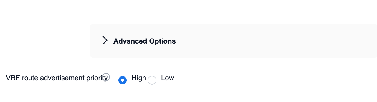
4. Configure VRF route advertisement priority
SITE-A
Set VRF route publishing priority to be high
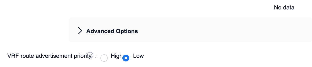
SITE-B
Set VRF route publishing priority to low
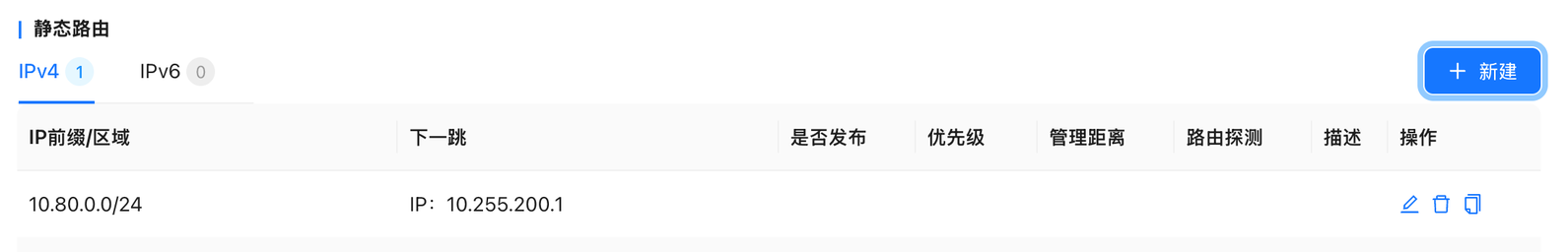
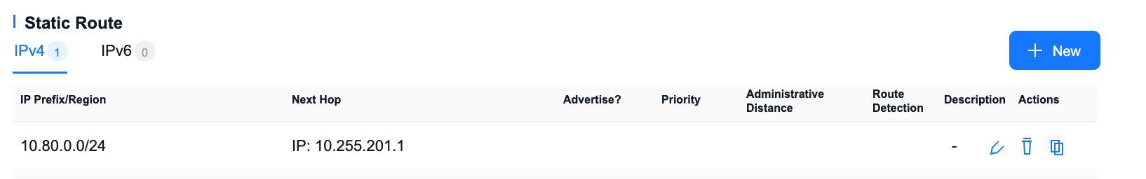
5. Configure static routing (SITE-A)
In the VRF configuration, enter LAN-VRF routing-static routing
- Add static route
- IP prefix: Transit Gateway CIDR: e.g. 10.80.0.0/24
- Next hop: The gateway of the subnet where the LAN port is located 10.255.200.1
6. Configure static routing (SITE-B)
In the VRF configuration, enter LAN-VRF routing-static routing
- Add static route
- IP prefix: Transit Gateway CIDR: e.g. 10.80.0.0/24
- Next hop: The gateway of the subnet where the LAN port is located 10.255.201.1
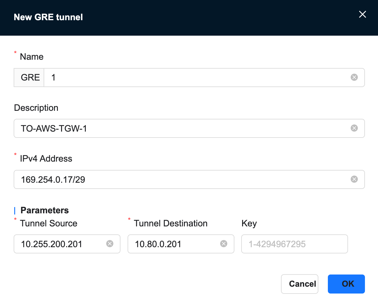
7. Configure GRE tunnel
For address information, refer to TGW’s Connect configuration.
1. Add gre tunnel at SITE-A
[Site]-[VRF Configuration]-[GRE Tunnel]-[New]
- Local address: LAN port ip
- Remote address: tgw gre address configured by TGW's Connect
- IPv4 address: Peer BGP address of the TGW's Connect configuration
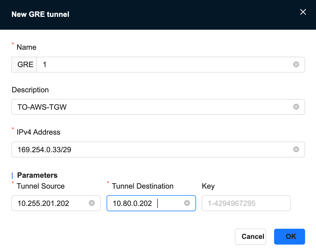
2. Add gre tunnel at SITE-B
[Site]-[VRF Configuration]-[GRE Tunnel]-[New]
- Local address: LAN port ip
- Remote address: tgw gre address configured by TGW's Connect
- IPv4 address: Peer BGP address of the TGW's Connect configuration
3.5 Confirm configuration status
After the above configuration is completed, confirm that the BGP status is UP in the transit gateway connection-Connect peering.

4. Failover mechanism
- When the primary NE900 (SITE-A) fails or the session with TGW BGP is interrupted, TGW automatically revokes the primary route and selects the route of the backup NE900
- After recovery, the main NE900 re-establishes the BGP session, and the AS_PATH short route becomes the first choice again
5. View routing information
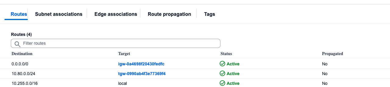
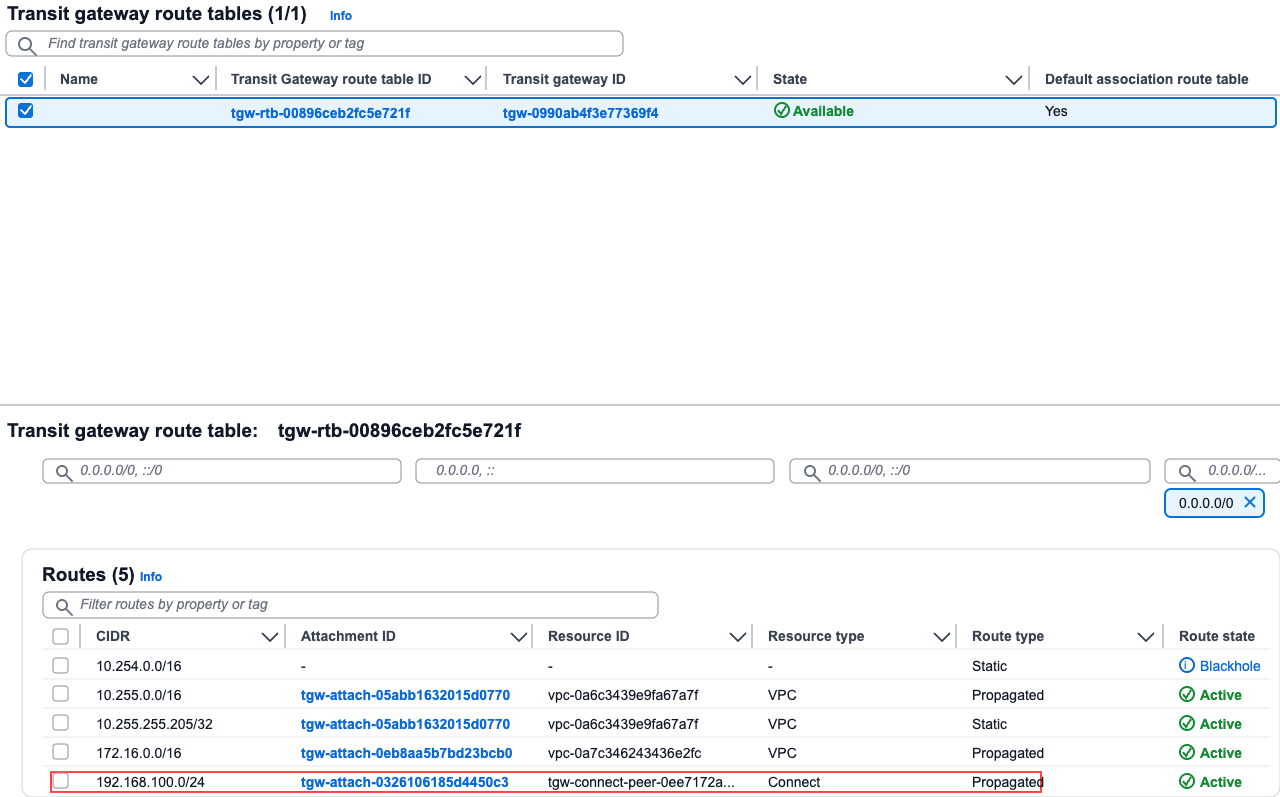
View routes at TGW
- Transit gateway - transit gateway routing table, select our routing table, and confirm receipt of the SITE-C route in the routing information
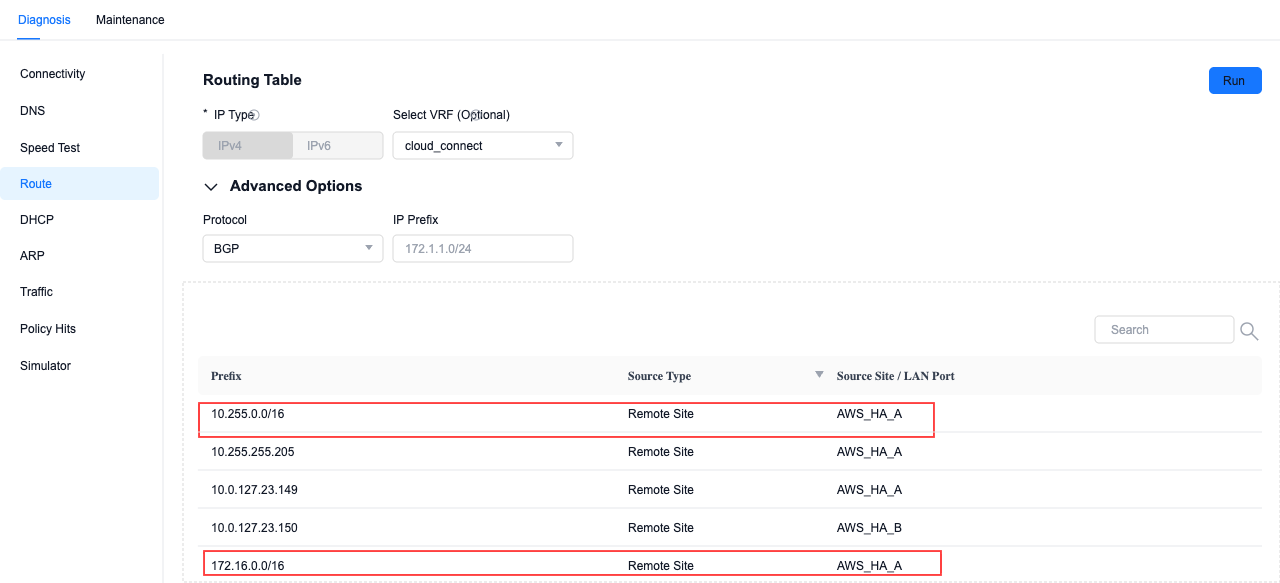
View routes for SITE-C site on SASE
- In Site-Monitoring-Diagnosis, by querying BGP routing, you can see that the routes of VPC1 and VPC2 have been learned.
References
- TGW description: https://docs.aws.amazon.com/vpc/latest/tgw/what-is-transit-gateway.html
- Connect attachments: https://docs.aws.amazon.com/vpc/latest/tgw/tgw-connect.html