Subinterface and port definitions
Function overview
The device supports the creation of multiple sub-interfaces (Sub-interfaces) on a single physical interface. Each sub-interface can be configured with an independent VLAN ID to achieve multi-service isolation. At the same time, sub-interfaces can be assigned network roles (such as WAN / LAN), and corresponding routing policies, access control, security policies, etc. can be applied. This mechanism allows flexible network topology construction and service deployment under limited physical resources.
Interface role description
Configuration instructions
- The interface role must be set to "None" before it can be switched to other valid roles (such as WAN, LAN, etc.).
- The configured WAN port cannot be reduced and only supports new additions.
- WAN ports must be added in sequence (such as WAN1 → WAN2 → WAN3).
| Interface type | Whether sub-interfaces can be configured | Configurable roles | Whether they can be added to Bond |
|---|---|---|---|
| Physical port | ✅ | WAN / LAN / HA / Management port / Bond member/virtual line | ✅ |
| └─ Subinterface | — | WAN / LAN | ❌ |
| Bond | ✅ | LAN / HA | |
| └─ Subinterface | — | LAN | |
| Virtual line member | ❌ | WAN side/LAN side | ❌ |
| LTE | ❌ | WAN | ❌ |
| Wi-Fi | ❌ | LAN | ❌ |
Interface number limit
| Role type | Quantity limit description |
|---|---|
| WAN | SupportsWAN1~WAN7, up to 7 configurations. |
| LAN | Unlimited number by default; when security (SWG) function is enabled,supports up to 4 valid LAN interfaces. |
| Sub-interface | Multiple sub-interfaces can be created for each physical port or Bond interface, and theVLAN ID range is 1~4094. In principle, the quantity is not limited. |
| Management port | No need to configure, up to 1 can be configured for management access (such as SSH/Web). |
| Virtual Line | Up to 1 virtual link can be configured. |
| Wi-Fi | For Wi-Fi enabled devices,up to 6 SSIDs can be configured (excluding management SSID). |
| Virtual machine/cloud host | In a virtualization deployment scenario,A single virtual machine/cloud host supports a maximum of 10 ports (physical port + sub-interface). |
Get and apply existing interface configuration
"Tenant" → "Config" → "Site" → "Edit Site" → "Port Definition"
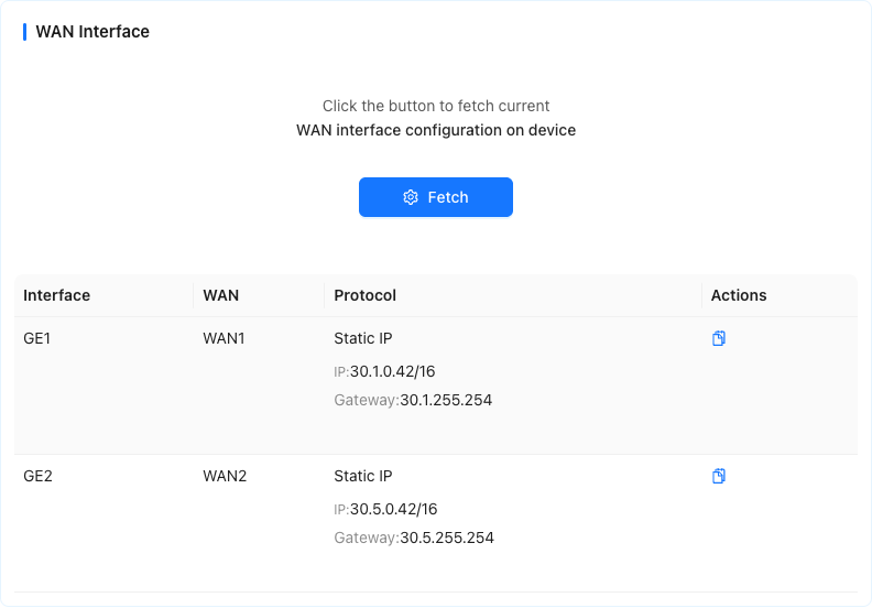
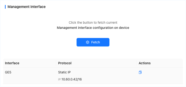
This page supports the function of [Get WANport configuration] or [GetManagement port configuration] function to quickly load the existing interface configuration (including interface, WAN serial number, VLAN ID, interface role, etc.) in the current site, and can be applied to the current device interface with one click.
This function is suitable for scenarios such as device replacement and configuration recovery. It can avoid repeated manual filling, improve configuration efficiency and reduce error rates.
📋 Function description
Supports two types of configuration acquisition:
[Get WAN port configuration information]: Get the existing WAN interface configuration in the site.
[Get management port configuration information]: Get the existing management port configuration in the site.
The configuration content obtained by the system includes:
The physical interface or VLAN sub-interface to which it belongs
VLAN ID (if subinterface)
Interface role (WAN/management port)
WAN number
If the original configuration contains a sub-interface (that is, with VLAN ID), the system will automatically create a corresponding VLAN sub-interface, and then apply the configuration items to the sub-interface.
Users can preview the obtained configuration details in the interface
After clicking [Apply to Interface], the system will apply the selected configuration to the corresponding port of the current device.
🧭 Operation steps
- Click [Get WANport configuration] or [Getmanagement port configuration] on the page.
- View the pop-up configuration list and confirm each configuration item (such as port, VLAN ID, role, WAN number, etc.).
- If configured as a sub-interface, the system will prompt the user to manually create the corresponding VLAN sub-interface before applying it.
- Click [Apply to Interface], and the system will automatically complete the interface configuration.
⚠️ Notes
- Only supports obtaining existing and successfully delivered interface configurations at the current site.
- If the interface of the target device is already occupied (such as an existing role), a conflict will be prompted when applying the configuration.
- The interface configuration after application can still be modified manually and will not be locked.
Add VLAN subinterface
"Tenant"→"Config"→"Sites"→"Edit Site"→"Port Definition"
This page is used to create a VLAN sub-interface on an existing physical interface to achieve multiple VLAN isolation and interface role assignment.
📋 Field description
| Field name | Description |
|---|---|
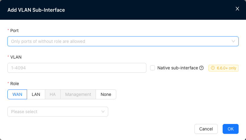
| Port | Select the physical interface interface used to create the subinterface. Note: To create a sub-interface, the interface role of the selected port must first be set to "None", otherwise it cannot be created. |
| VLAN | Enter VLAN ID, the value range is 1~4094. The VLAN ID identifies the VLAN to which this subinterface belongs. |
| Role | Specify network roles for sub-interfaces, including: -WANis used to connect to the upstream network or public network -LANis used to access intranet terminals -HAis used for device high-availability links -Management portis used for device management/local login -None No role is assigned (default). |
🧭 Operation steps
- Make sure the role of the target physical port or Bond port is set to "None".
- Click the "Port" drop-down box and select the physical interface.
- Fill in the VLAN ID (for example: 100) in the VLAN field.
- Select the role of the subinterface (such as WAN).
- If the role is WAN, you need to select an additional WAN number.
- Click OK to complete the addition.
⚠️ Notes
- A physical interface can be configured with multiple sub-interfaces, but each VLAN ID must be unique.
- WAN After the sub-interface is created, it cannot be deleted but can only be added, and the number must be configured in sequence (for example: WAN1 → WAN2).
- The sub-interface cannot be added to the Bond aggregation group. If aggregation is required, please operate on the main interface.
Add aggregation port
"Tenant"→"Config"→"Sites"→"Edit Site"→"Port Definition"
This page is used to aggregate multiple physical interfaces into a Bond interface to achieve link load balancing or redundancy and improve network reliability and throughput.
📋 Field description
| Field name | Description |
|---|---|
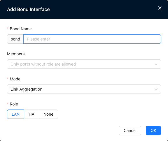
| Aggregation port name | Set the serial number of the new Bond, the serial number range is 1-8. |
| Aggregation port members | Select the physical interface that needs to participate in aggregation. ⚠️ Only physical interfaces with interface role "None" can be added as aggregate members. |
| Mode | Set link aggregation mode. |
| Role | Assign network roles to the aggregation port, including: -[LAN]for access to intranet terminals -[HA]for high-availability links -[None] No role is assigned (default). |
🧭 Operation steps
- Set the role of the physical interface to be aggregated to "None".
- Click the "Aggregation Port Name" field and enter the Bond interface name (such as
bond1). - Select the interface (such as
GE1,GE2) in the "Aggregation Port Member" drop-down box. - Select the working mode of link aggregation (such as LACP).
- Set the role of the aggregation port (such as LAN).
- Click [OK] to complete the creation.
⚠️ Notes
- The same physical interface cannot be added to multiple Bond interfaces at the same time.
- After the Bond interface is created, you can continue to add VLAN sub-interfaces to it for multi-VLAN network isolation.
Add SSID
"Tenant"→"Config"→"Sites"→"Edit Site"→"Port Definition"
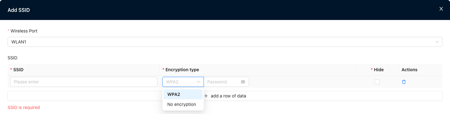
This page is used to add SSID to devices with wireless functions to implement wireless network access configuration. It supports setting encryption methods, passwords, SSID hiding and other parameters.
📋 Field description
| Field name | Description |
|---|---|
| Interface | Select a physical interface on the device that has wireless capabilities (such as WLAN1). This interface is used to broadcast the configured SSID. |
| SSID | Set the wireless network name (SSID), supports Chinese, English and numerical combinations, and cannot be empty. |
| Encryption method | Configure the encryption type of the wireless network, currently supported: -WPA2: Recommended encryption method, password required - No encryption: Open network, no password |
| Password | When selecting WPA2 encryption method, you need to set a password (8~63 characters) to access the SSID. |
| Hide | When checked, the SSID will not be broadcast and only supports manual connection. |
| Operation | Support deleting the current SSID configuration item. |
🧭 Operation steps
- Click the "Interface" drop-down box and select the wireless interface that broadcasts the SSID (such as WLAN1).
- Enter the wireless network name in the SSID field.
- Set encryption method:
- If WPA2 is selected, please enter the access password.
- If No Encryption is selected, the password field will automatically be disabled.
- Check the "Hide" option as needed to decide whether to broadcast the SSID.
- Click [OK] to complete the configuration.
⚠️ Notes
- A device supports configuration of up to 6 SSID.
- It is not recommended to set up an open (unencrypted) network to avoid security risks.
- SSID names should be concise and concise, avoiding special characters or very long strings.
- After configuration, it needs to be referenced on the "vrf configuration" page to take effect.
Add a network card to the virtual device and bind the logical interface
- In a virtualization deployment scenario, dynamically add a new network card to the running SD-WAN virtual device and bind it as a logical interface (such as GE5, GE6) through the command lineorUI interface.
- After the interface is bound, standardized configuration (role assignment, sub-interface, address, etc.) can be performed in the controller without entering the device for additional configuration.
- This function is suitable for scenarios such as device hot-plugging, interface expansion, HA dual-machine synchronization, etc. It supports the concurrent addition and configuration of multiple network cards, significantly improving flexibility and deployment efficiency.
📋 Function description
- After adding a network card to the virtual platform, the device automatically recognizes the new network card interface name (such as ens225)
- Bind the physical interface name to the logical interface (such as GE6) through commands or UI
- After the binding is completed, the interface can be configured as a standard interface in the site (such as WAN / LAN / management port)
- Supports concurrent binding of multiple interfaces, supports sub-interface and Bond operations, and supports HA dual-machine consistency check
🖥️ UI operation method
Applicable conditions:
- Controller version Mars and above> - Device modelNE900, software version ≥ 6.5.0> - User hasCPE_NE900_PORT_U permission
- Add one or more network cards to the target device in the virtualization platform (such as VMware vSphere)
- Log in to the controller and enter the target site → Monitoring→Site→Operation and Maintenance→Other page
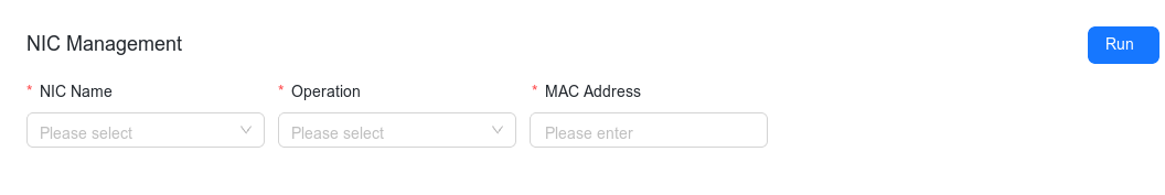
- The page provides the following functions:
- New: Select the new physical network card, fill in the logical interface name (such as GE6), fill in the mac address (the address is separated by ‘:’), and bind.
- Edit: Modify existing binding information.
- Delete: When deleting a binding, just select the port. There is no need to fill in the MAC address.
- After the binding is completed, the interface can be configured in a standardized manner such as roles, VLAN, and sub-interfaces in the controller.
>_ Command line operation mode
Applicable conditions:
- Controller version Earth and above> - Device modelNE900, software version ≥ 6.4.0
- The user has CLI operation permissions
Add virtual network card Add one or more network cards to the target device in a virtualization platform (such as VMware vSphere).
Log in to the device and view the new network card name
ip link show
- Bind the new network card as a logical interface Use the following command to bind the [physical interface name], for example: ens225, to the [logical interface name] recognized by the controller, for example: GE6:
config -u ports/GE6 -m put '{"name":"GE6","ifname":"ens225"}'
Enter the controller site configuration and complete interface initialization (role/VLAN/sub-interface, etc.)
To unbind or rebind an interface, it is recommended to first unbind related configuration dependencies (such as Bond, sub-interface) and then execute the following command:
config -u ports/GE6 -m delete
🤝 HA scene description
- The active and backup devices need to add network cards respectively, and execute the same command to bind them to the same logical interface name (such as GE6)
- The controller will verify whether the interfaces of the two devices are consistent to ensure that the active and standby devices can switch to each other and that the configurations do not conflict.
- If the secondary device is not bound to the corresponding interface, the controller will prompt "Interface inconsistent" when saving and will not save it.
⚠️ Notes
- Only available on device versions that support this feature
- The same physical interface is not supported to be bound to multiple logical interfaces. Binding conflicts will prompt an error.
- The sub-interface can only be created after the interface is successfully bound.
- It is recommended that the total number of virtual machine interfaces does not exceed 10
- For sub-interface functions, please refer to: Add VLAN sub-interface
Device GUI supports VLAN sub-interfaces
In some deployment scenarios, the site uses a single Trunk line to carry multiple VLAN (such as access network and management traffic), and the new device has not yet been registered with the controller. At this time, the configuration cannot be delivered from the platform side.
In order to enable the device to complete network connectivity through its own interface before registration, the Device GUI provides the ability to locally configure the VLAN sub-interface. Users can directly add the VLAN sub-interface to the physical port through the device page and specify the IP, thereby realizing communication between the device and the controller.
📋 Function description
- Supports entering configuration mode through Device GUI → Configuration → WAN before the device is registered.
- You can add VLAN sub-interface to any physical port
- After the configuration takes effect, the device can access the controller through the VLAN sub-interface to register and go online.
🧭 Operation steps
- Use a network cable to connect the device management port or the default LAN port to access the device GUI (such as
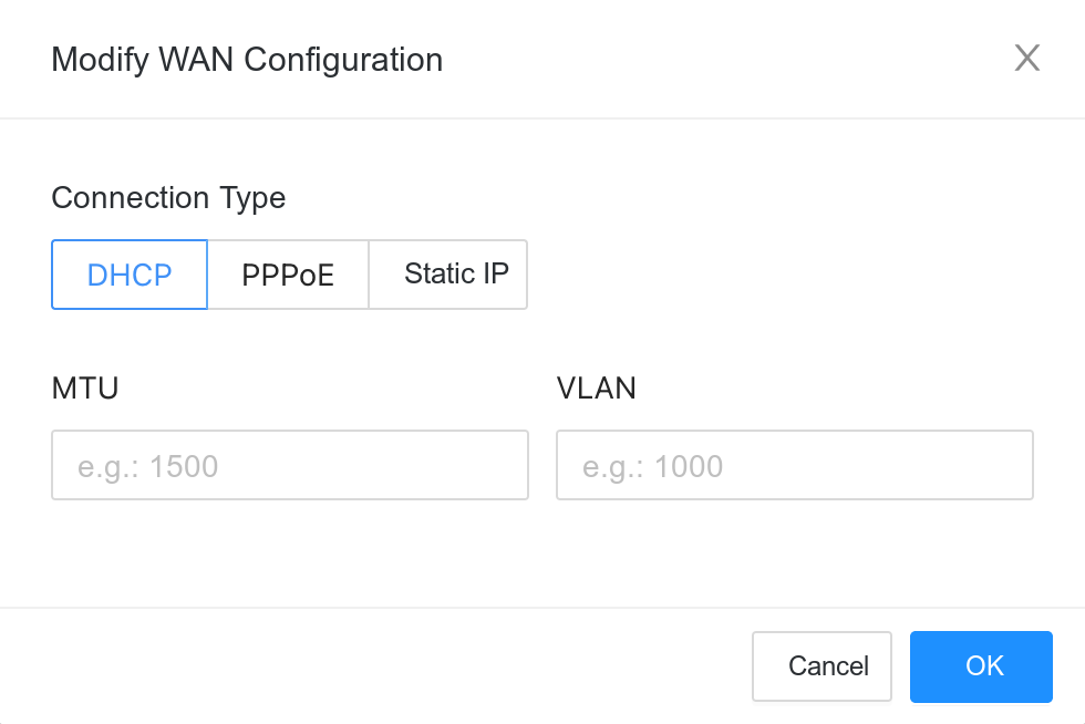
192.168.1.1). - Enter the [Network Configuration] page and click on the physical port to be configured (such as GE1).
- Edit "Modify WAN Configuration" and modify the VLAN ID.
- Save and apply the configuration and the device will attempt to connect to the controller through the VLAN sub-interface.
- After the controller receives the registration request, the device enters the online process.
⚠️ Notes
- The VLAN sub-interface configuration is only used for initial communication before registration. This configuration will not be synchronized to the controller, but the controller's configuration will be delivered and overwrite the configuration on the DeviceGUI.
- There is no need to restart the device after the configuration is completed, it will take effect immediately after application.