Transparent mode
1. Function Overview
Transparent mode is a working mode in which the device operates under the Layer 2 forwarding architecture. In this mode, the source and destination IP address information of the data packet is not changed, but the traffic is forwarded in the network through Layer 2 bridging to achieve transparent data transmission.
In transparent mode, the device is unaware of the upper-layer network topology and can implement functions such as traffic monitoring, policy control, and security detection without affecting the existing network structure.
2. Supported device models
- NE206
- NE600
- NE800
- NE900
Devices that support hardware bypass
- NE206BX
- NE600MZ
3. Deployment scenarios
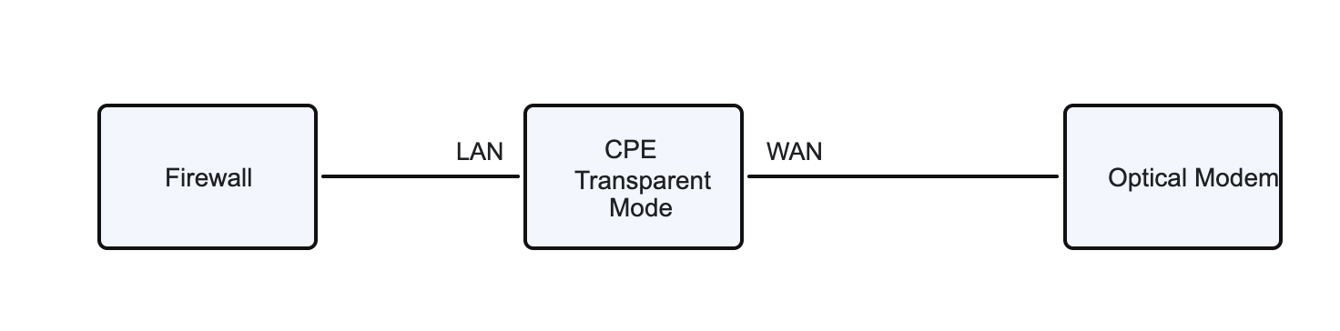
1. Scenario 1, the transparent mode device is deployed between the firewall and the optical modem
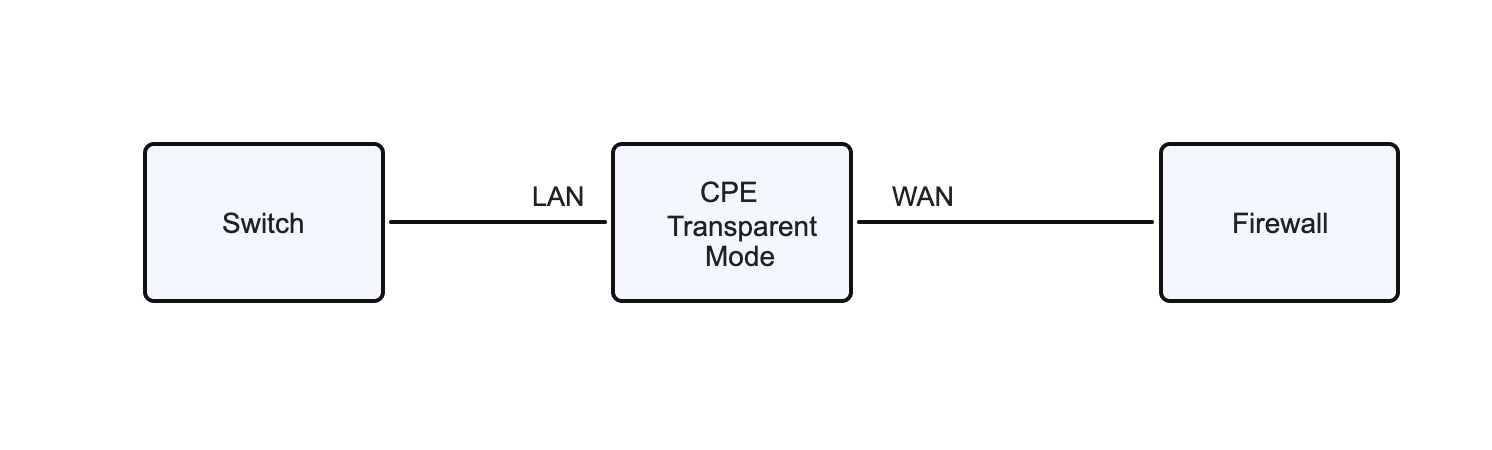
2. Scenario 2, the transparent mode device is deployed between the switch and the firewall
4. Configuration instructions
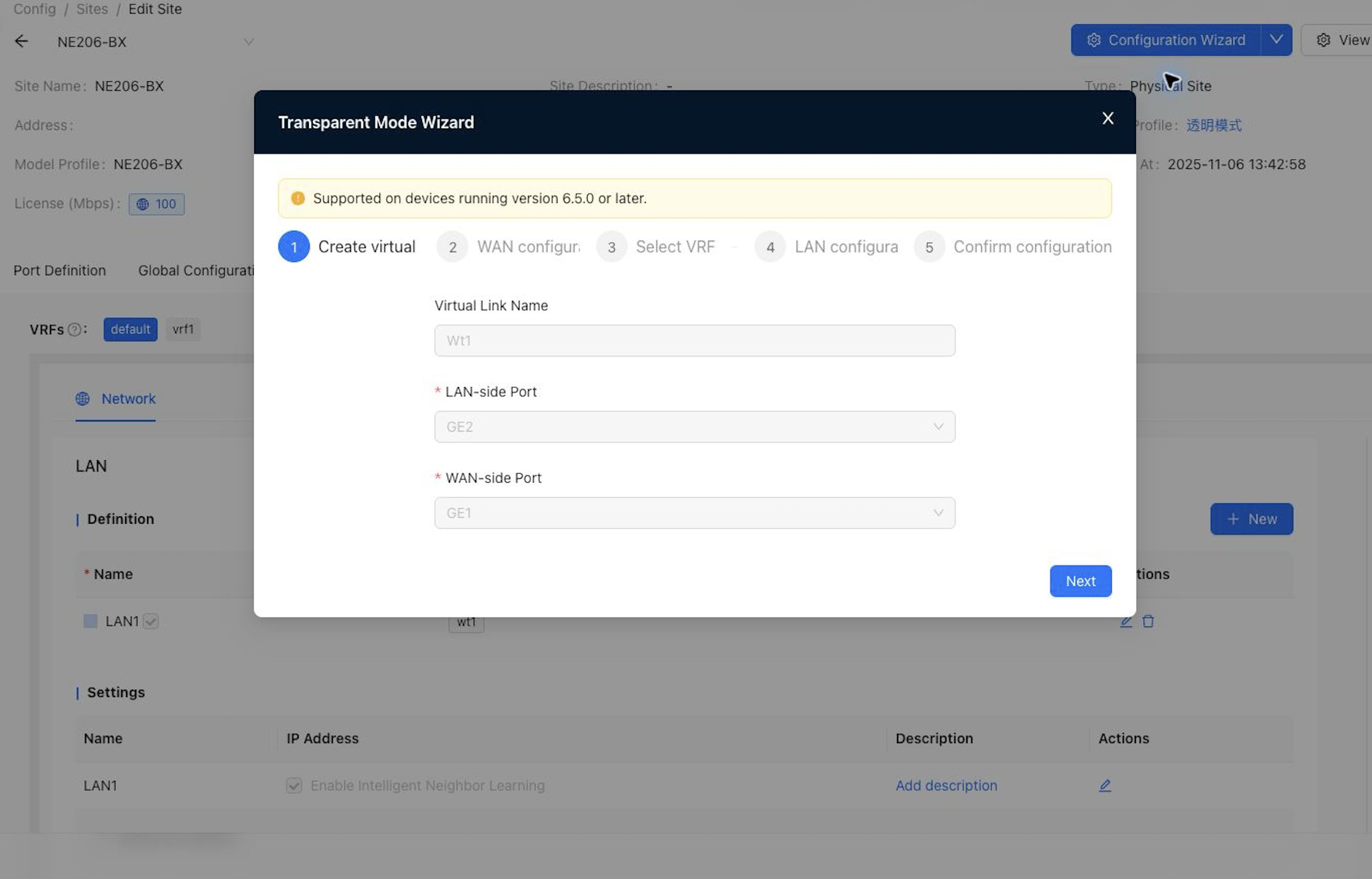
This function can be configured through the configuration wizard, and the location corresponding to each configuration item is explained below the configuration.
1. Port definition
"Tenant"→"Config"→"Site"→"Edit Site"→"Port Definition"
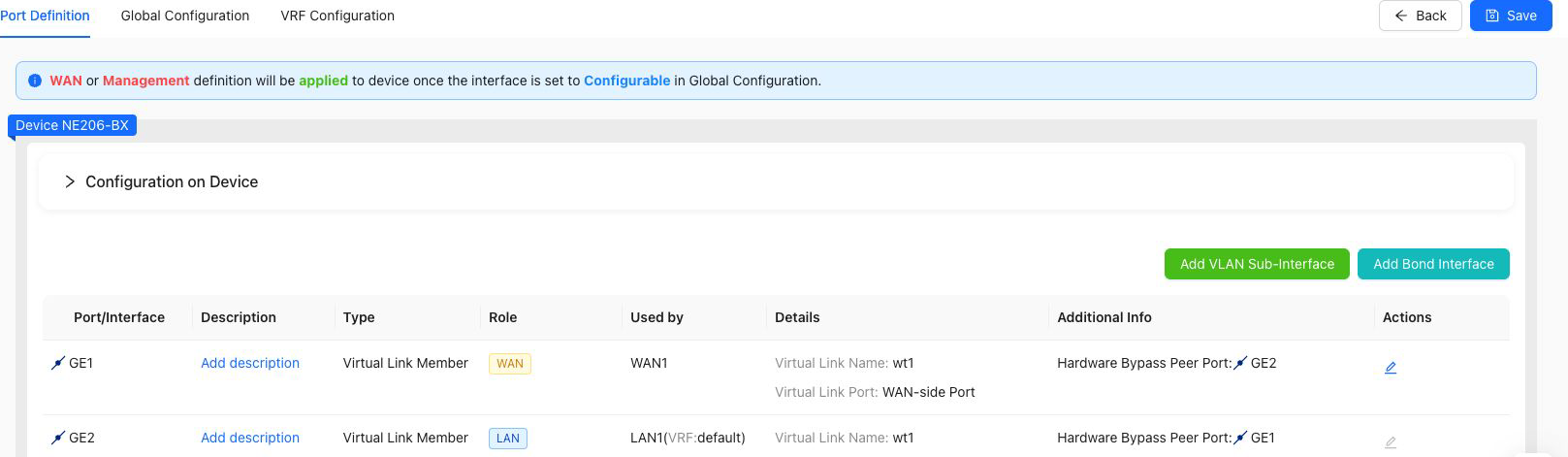
Before adding a virtual line, you need to define the role WAN LAN of the virtual line member port at the port definition.
Notes
- NE206BX device, virtual lines are pre-configured and do not need to be added manually.
- NE600MZ, it is recommended to choose an expansion port with bypass function.
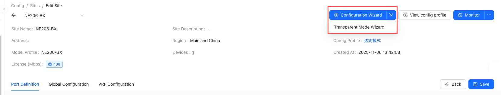
2. Configuration Wizard
"Tenant"→"Config"→"Site"→"Edit Site"→"Configuration Wizard"
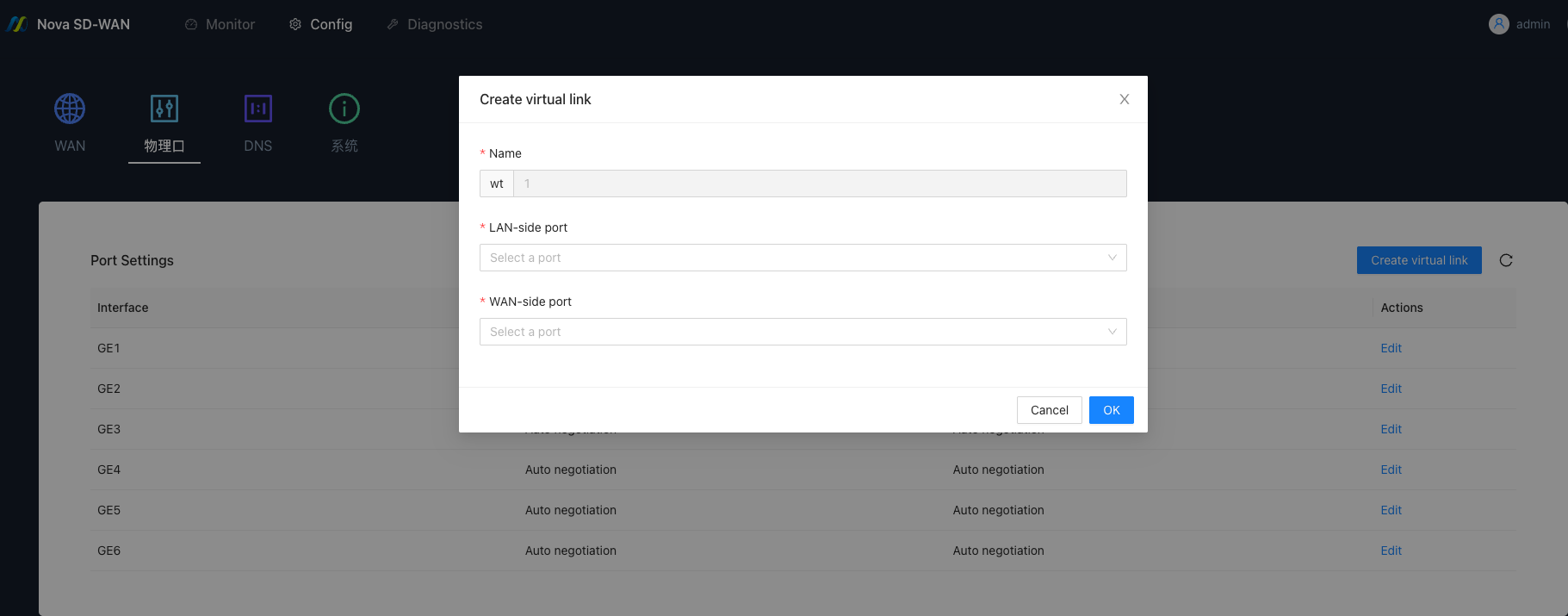
3. Add a dotted line
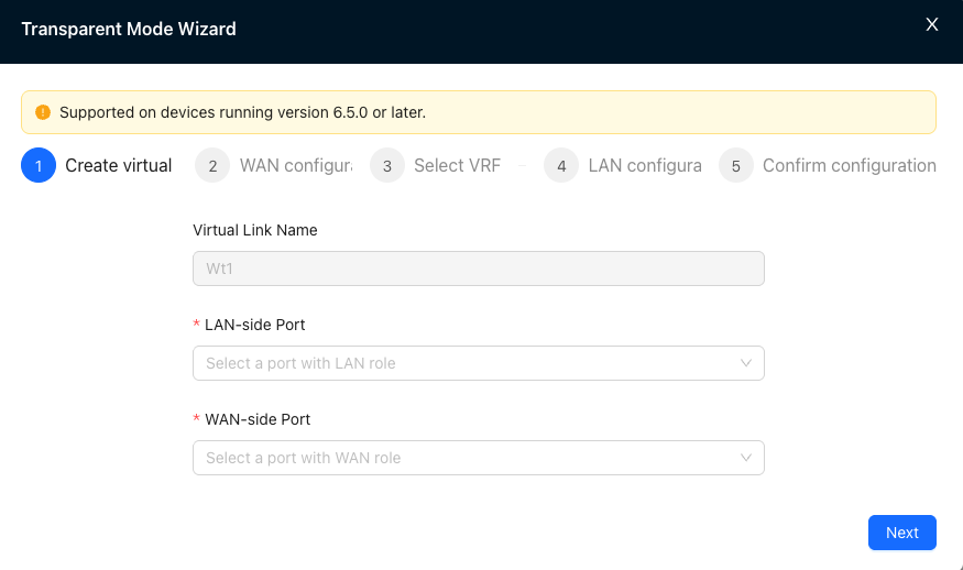
Corresponding configuration location:
"Tenant"→"Config"→"Site"→"Edit Site"→"Port Definition"→"Add Virtual Line"
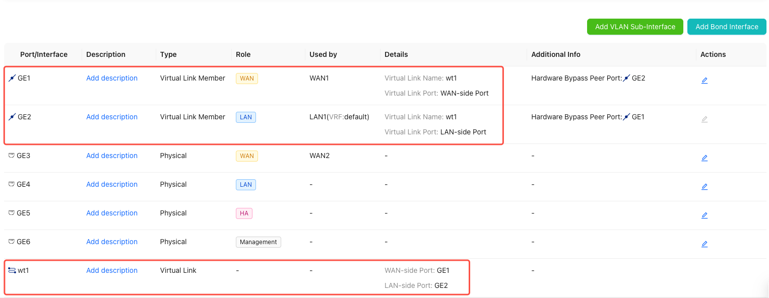
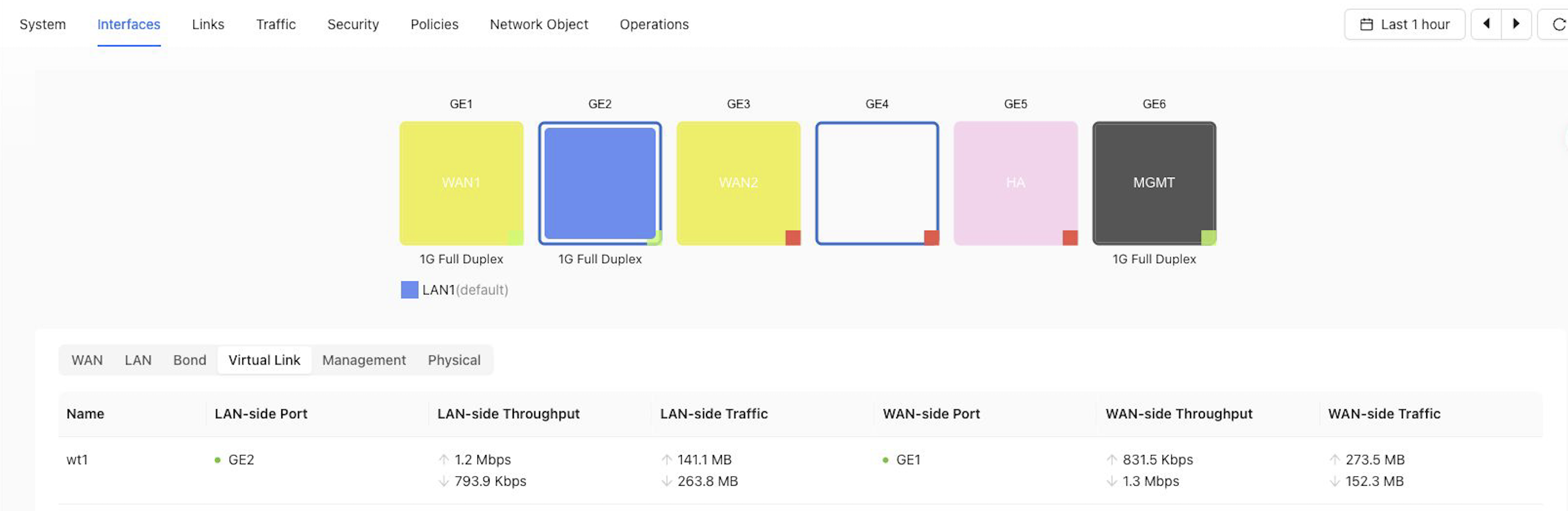
After the addition is completed, you can view the port information of the virtual line at "Tenant" → "Monitor" → "Site" → "Port" → "Virtual Line".
Configuration instructions
- Before configuring a virtual line member interface, you must first complete the interface role definition at the port definition:
- WAN side port: Only interfaces with role WAN can be selected.
- LAN side port: Only interfaces with role LAN can be selected.
Notes
- Currently only adding a dashed line is supported.
- Virtual line member interfaces do not support VLAN sub-interfaces and aggregate interfaces.
- Sites using old templates do not support transparent mode and cannot create virtual lines.
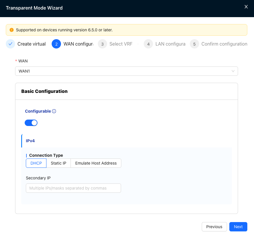
4. WAN configuration
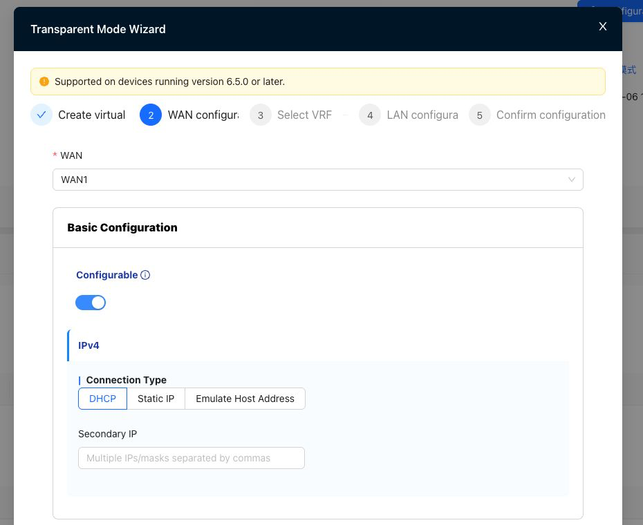
Corresponding configuration location:
"Tenant"→"Config"→"Site"→"Global Configuration"→"WAN"
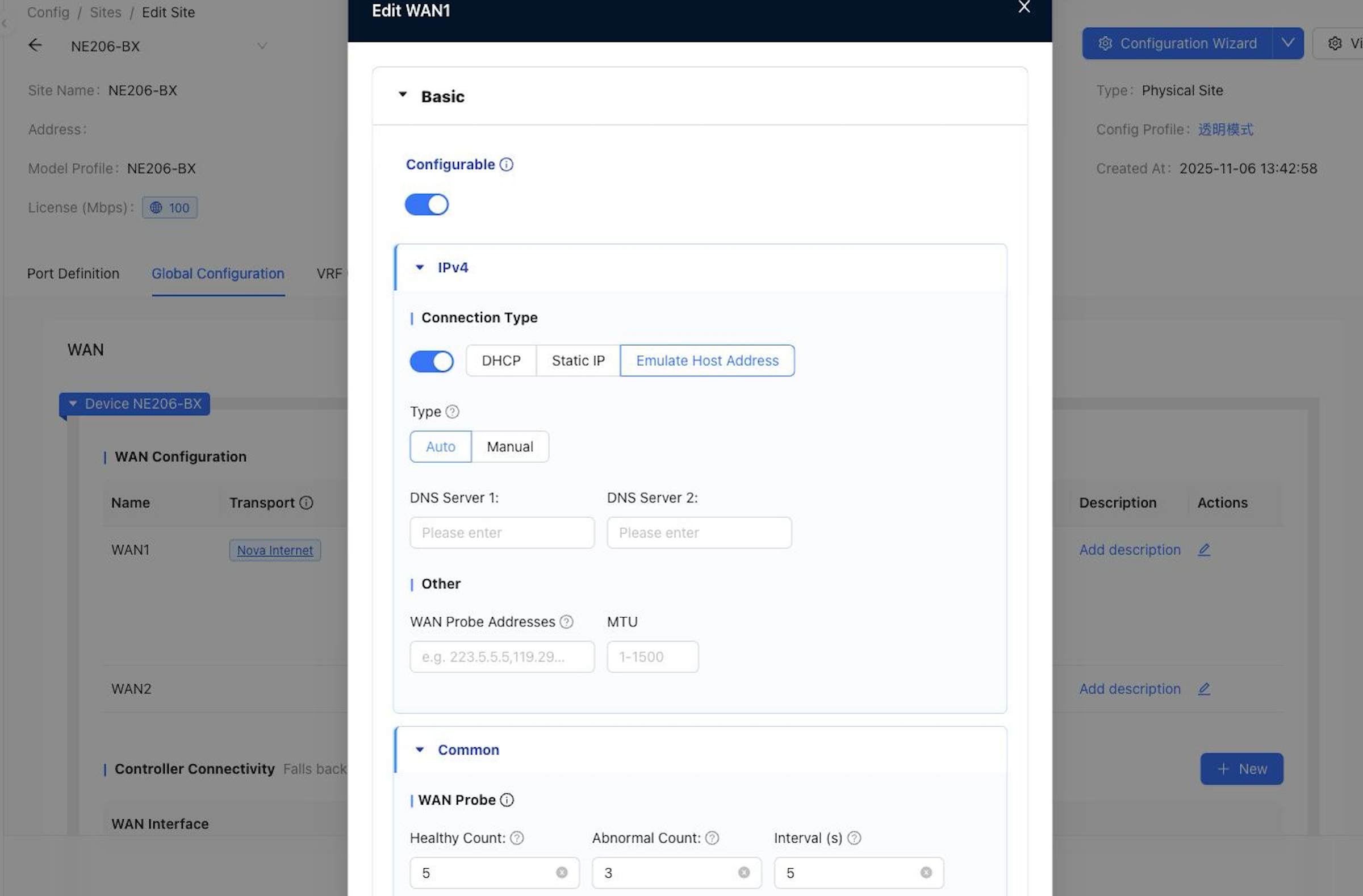
Configuration instructions
- WAN supports four connection types: DHCP, static IP, simulated host (manual), and simulated host (automatic).
- Simulate host (manual): Simulate the specified LAN side host address ip, no need to assign an ip address separately.
- Simulated host (auto): Automatically select and simulate the LAN side host ip based on traffic, no need to assign an ip address separately.
- If there is no host traffic in the environment, the host IP cannot be learned.
5. Turn on transparency mode
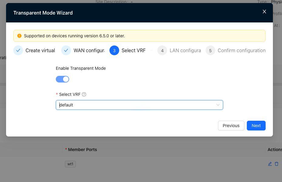
Corresponding configuration location:
"Tenant"→"Config"→"Site"→"Global Configuration"→"Turn on transparent mode"
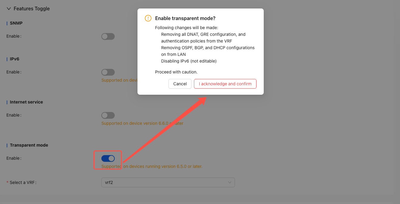
Notes
- Single arm is not supported.
- Transparent mode does not support HA.
- Only supports enabling transparent mode for one VRF.
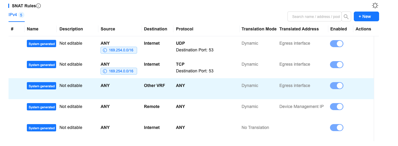
- After transparent mode is turned on, IPV6, SNMP, LAN-side DHCP, LAN-side OSPF, LAN-side BGP, DNAT, and GRE tunnels are not supported.
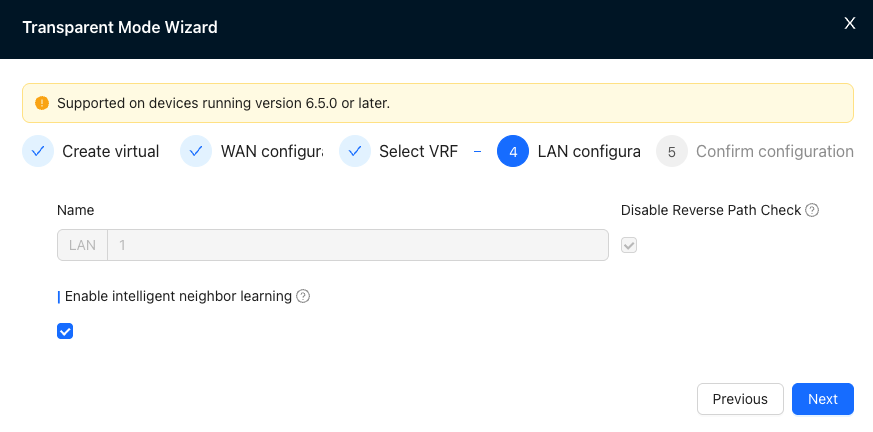
6. LAN configuration
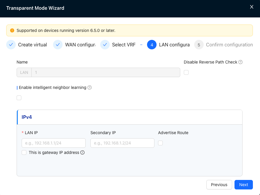
Corresponding configuration location:
"Tenant"→"Config"→"Site"→"vrf configuration"→"LAN"
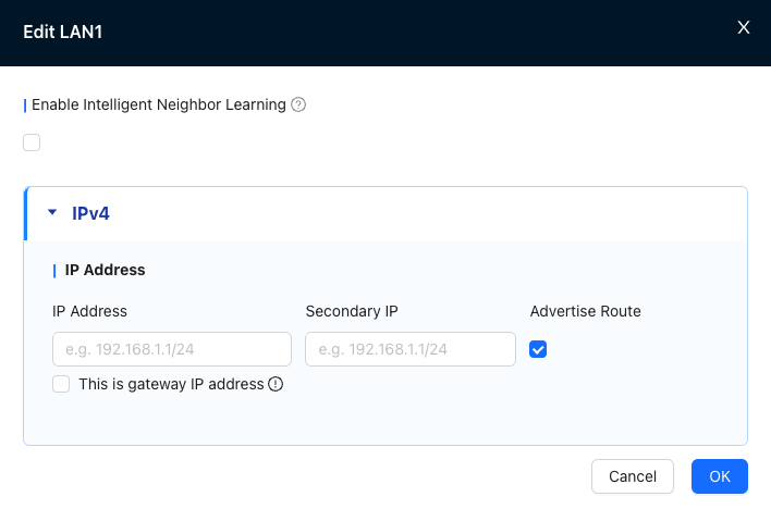
Configuration instructions
LAN configuration-smart neighbor learning
The system will learn IPv4 traffic and obtain neighbor address mapping, without configuring LAN IP.
In this mode, the system will automatically generate and deliver some default policies to assist in traffic forwarding.
LAN configuration - static IP
Resolve the host address on the LAN side via regular ARP.
When the LAN IP is configured as the WAN gateway IP, you need to check "This IP is the gateway IP".
When the LAN IP is a separately assigned IP address, there is no need to check "This IP is a gateway IP".
In this mode, the system will automatically generate and deliver some default policies to assist in traffic forwarding.
Notes
- Transparent mode only supports configuring one LAN.
- The transparent mode LAN port can only be configured as wt1 port.
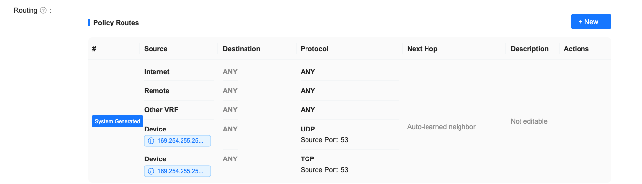
- When the LAN is configured for intelligent neighbor learning, if you need to publish the LAN segment route to the remote end, you need to manually add a route with the next hop: the interface directly connected to the LAN.
- When the LAN is configured for smart neighbor learning or a separately assigned static IP address, if the host needs to communicate with the gateway, it needs to manually add a route to the WAN gateway with the next hop pointing to: WAN.
5. Device management interface
"Config"→"Physical Port"→"New Virtual Line"
"Config"→"WAN"→"New WAN"
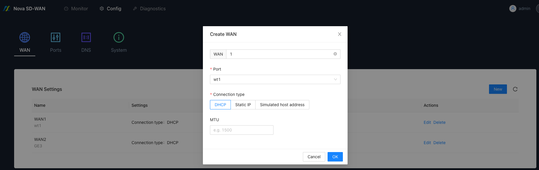
Notes
- The WAN port needs to be selected as wt1.
- When the connection type is selected as simulated host address (automatic), if there is no host traffic in the environment, the device will not be able to connect to the controller.
6. Use restrictions
| WAN Connection Type | LAN - Smart Neighbor Learning | LAN - Static IP |
|---|---|---|
| DHCP | ✅ | ✅ |
| Static IP | ❌ | ✅ |
| Simulated host address (manual) | ❌ | ✅ |
| Simulated host address (automatic) | ✅ | ❌ |
- Transparent mode does not support forwarding packets with ttl<3, such as OSPF and eBGP packets.
- Transparent mode sites in Hub-Spoke networking are not supported as hub sites.
7. Scenario examples
Scenario 1: Transparent mode plus multiple vrf offloading
1. Background
A company hopes to achieve intelligent accelerated offloading of overseas access traffic by deploying CPE equipment between the egress firewall and the optical modem, while keeping local business traffic on its original path to improve cross-border access performance and minimize the impact on the existing network.
2. Implementation
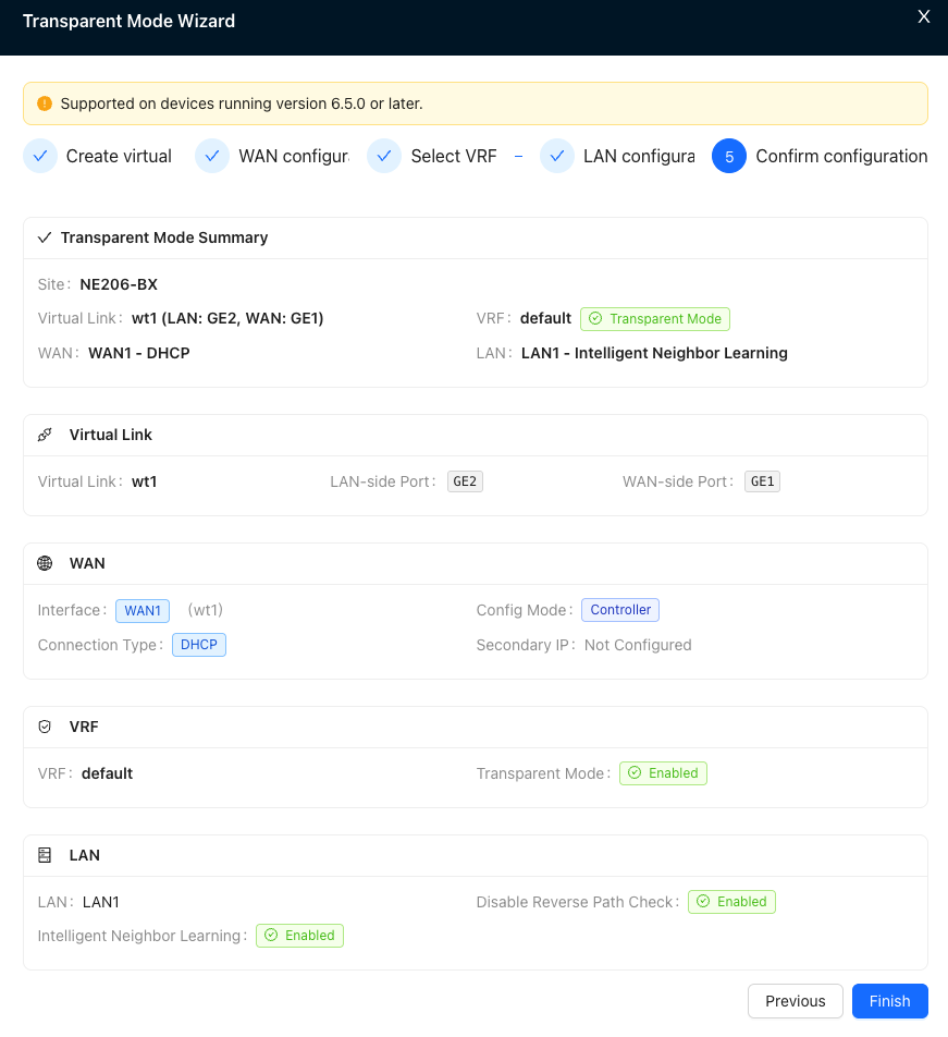
2.1 Transparent mode configuration
- Configure the port used by the virtual line in the port definition first, such as: GE1, WAN; GE2, LAN
- Create a virtual line, select GE2 for the LAN side port, and select GE1 for the WAN side port.
- Configure WAN, select DHCP as the connection type
- Select default VRF to enable transparent mode

- LAN side configuration enables intelligent neighbor learning
- Check the configuration and click Submit after confirming it is correct.
2.2 Acceleration configuration
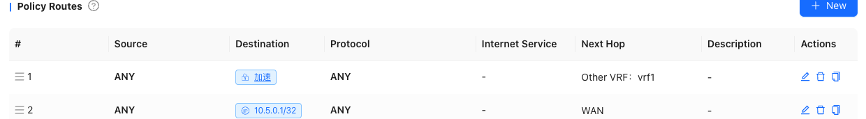
In the Nova Gateway advanced configuration of Nova Gateway-VRF1, configure the acceleration gateway, configure and publish two static routes of 0.0.0.0/1 and 128.0.0.0/1 in the gateway, and the next hop; WAN.
In the site-default VRF, add two policy routes, source: any, destination: IP or domain name that needs to be accelerated, next hop: vrf1; source: any, destination: 10.5.0.1/32 (WAN gateway IP), next hop; WAN.
In the site-default VRF, configure the domain name proxy resolution policy to proxy overseas domain names to a specific overseas DNS server for resolution.
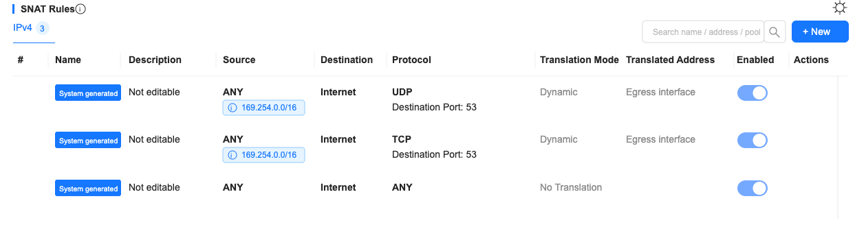
In site-vrf1, add ACL firewall policy, source: other vrf, destination: any, action allowed.
In site-vrf1, add snat policy, source: any, destination: remote site, conversion mode: dynamic nat, converted address: 100.127.1.53 (device management IP).
